

0
Owner's of the Cisco Systems Switch Cisco Nexus Switch gave it a score of 0 out of 5. Here's how the scores stacked up:

Send document comments to nexus7k-docfeedback@cisco.com
5-3
Cisco Nexus 7000 Series Hardware Installation and Reference Guide
OL-18634-01
Chapter 5 Connecting the Cisco Nexus 7000 Device to the Network
Creating an Initial Device Configuration
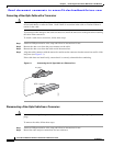
Step 3 Route the RJ-45 rollover cable through the center slot in the cable management system and then to the
console or modem.
Step 4 Connect the other end of the RJ-45 rollover cable to the console or to a modem that can connect to the
console. If the console or modem cannot use an RJ-45 connection, use one of the following adapters from
the console cable connector kit:
• RJ-45/DSUB F/F adapter
• RJ-45/DSUB R/P adapter
• DB-9F/RJ-45F PC terminal
Creating an Initial Device Configuration
After you create the local management connection with a console, you must assign an IP address to the
device management interface so that you can then connect the device to the network.
As soon as you power up the device, it boots up and asks you a series of questions to configure the device.
This section explains how to configure the IP address that is required to connect the device to the
network. To enable you to connect the device to the network, you can use the default choices for each
configuration except the IP address. You can perform the other configurations at a later time as described
in the Cisco NX-OS Fundamentals Configuration Guide, Release 4.0.
Before you perform the initial device configuration, you must determine the IP address and netmask
needed for the following interfaces:
• Management (Mgmt0) interface
• Connectivity management processor (CMP) for the supervisor module in chassis slot 6
• CMP for the supervisor module in chassis slot 5
Note You should also know the unique name needed to identify the device among the devices in the network.
To define the IP addresses required for an initial device configuration, follow these steps:
Step 1 Power up the device by turning the power switch from STBY (standby) to Power on each power supply
installed in the device chassis.
The Input and Output LEDs on each power supply light up (green) when the power supply units are
sending power to the device.
The software asks you to specify a password to use with the device.
Step 2 Enter a new password to use for this device.
The software checks the security strength of your password and rejects your password if it is not
considered to be a strong password. To increase the security strength of your password, make sure that
it adheres to the following guidelines:
• At least eight characters
• Minimizes or avoids the use of consecutive characters (such as “abcd”)
• Minimizes or avoids repeating characters (such as “aaabbb”)
• Does not contain recognizable words from the dictionary


Find Your Products By Category
Please Login
