

0
Owner's of the Cisco Systems Switch Cisco Nexus Switch gave it a score of 0 out of 5. Here's how the scores stacked up:


Send document comments to nexus7k-docfeedback@cisco.com
6-8
Cisco Nexus 7000 Series Hardware Installation and Reference Guide
OL-18634-01
Chapter 6 Managing the Device Hardware
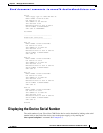
Power Supply Configuration Modes
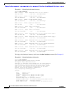
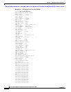
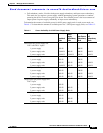
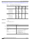
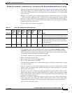
2 N7K-M132XP-11 423.50 8.47 423.50 8.47 Powered-Up
5 N7K-SUP1 210.00 4.20 210.00 4.20 Powered-Up
6 N7K-SUP1 210.00 4.20 210.00 4.20 Powered-Up
Xb1 N7K-C7010-FAB-1 60.00 1.20 60.00 1.20 Powered-Up
Xb2 N7K-C7010-FAB-1 60.00 1.20 60.00 1.20 Powered-Up
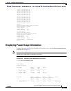
Power Usage Summary:
--------------------
Power Supply redundancy mode: PS-Redundant
Power Supply redundancy operational mode: Non-Redundant
Total Power Capacity 12000.00 W
Power reserved for Supervisor(s) 420.00 W
Power reserved for Fan Module(s) 2184.00 W
Power reserved for Fabric Module(s) 300.00 W
Power currently used by Modules 1197.00 W
-------------
Total Power Available 7899.00 W
-------------
switch#
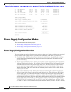
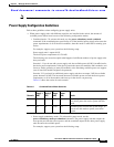
Power Supply Configuration Modes
This section includes the following topics:
• Power Supply Configuration Overview, page 6-8
• Power Supply Configuration Guidelines, page 6-11
Power Supply Configuration Overview
You can configure one of the following power modes to either use all of the available power provided
by the installed power supply units or to provide power redundancy when there is a power loss:
• Combined mode—Provides the maximum amount of available power by utilizing the combined
power output from all installed power supply units for device operations. This mode does not
provide redundancy.
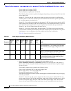
• Power-supply redundancy mode—Allows you to replace a power supply during device operations.
All power supply units are active. The available power is calculated as the least amount of power
available from all but one of the power supply units (N+1). The reserve power is the amount of
power output by the power supply that can output the most power. For example, if three power
supply units output 3
kW, 6 kW, and 6 kW, the available power is 9 kW (3 kW + 6 kW) and the
reserve power is 6
kW.
• Input source redundancy mode—Takes power from two electrical grids so that if one grid goes
down, the other grid can provide the power needed by the device. Each grid powers half of each
power supply (grid A is connected to the Input 1 receptacle on each power supply and grid B is
connected to the Input 2 receptacle on each power supply). The available power is the amount of
power output by the portions of power supply units connected to the same grid. For example, if three
power supply units are connected to a 110-V grid and a 220-V grid, each power supply outputs
1.2
kW for the 110-V grid and 3.0 kW for the 220-V grid. The available power would be 3.6 kW
(1.2
kW + 1.2 kW + 1.2 kW) and the reserve power would be 9.0 kW (3.0 kW + 3.0 kW + 3.0 kW).


Find Your Products By Category
Please Login
