

0
Owner's of the Cisco Systems Switch Cisco Nexus Switch gave it a score of 0 out of 5. Here's how the scores stacked up:

Send document comments to nexus7k-docfeedback@cisco.com
4-4
Cisco Nexus 7000 Series Hardware Installation and Reference Guide
OL-18634-01
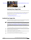
Chapter 4 Installing Power Supply Units
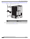
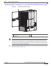
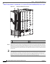
Connecting the Power Supply Units to AC Power
Note If you are using the combined power mode or power supply redundancy, you can connect both power
cables to the same 30 A circuit. If you are using the input source redundancy mode, you must connect
each power cable to separate 30 A circuits.
Warning
Take care when connecting units to the supply circuit so that wiring is not overloaded.
Statement 1018
Warning
This product relies on the building’s installation for short-circuit (overcurrent) protection. Ensure that
the protective device is rated not greater than:
250V, 20 A
Statement 1005
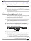
Step 3 Turn the power supply switch from STBY to ON.
Step 4 Verify that the power supply is receiving AC power by making sure that the INPUT and OUTPUT power
supply LEDs are lit and the FAULT LED is not lit or blinking. For an explanation of all the power supply
unit LEDs and the conditions that they indicate, see
Table C-5 on page C-5.
Note When you first activate the power supply, you can verify the functionality of the LEDs by checking that
each LED turns on for a couple of seconds.
If the Fault LED is blinking red, turn the power switch to STDBY, check the AC power connections on
the power supply unit and the AC power source, and then turn the power switch back to ON. The Input
and Output LEDs for the connected power supply units should be green and the Fault LED should be off.


Find Your Products By Category
Please Login
