

0
Owner's of the Cisco Systems Switch Cisco Nexus Switch gave it a score of 0 out of 5. Here's how the scores stacked up:

Send document comments to nexus7k-docfeedback@cisco.com
8-6
Cisco Nexus 7000 Series Hardware Installation and Reference Guide
OL-18634-01
Chapter 8 Removal and Installation Procedures
Replacing a Supervisor Module
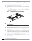
Step 9 If you are removing the module from a Cisco Nexus 7010 chassis, rotate the module 90 degrees
counterclockwise so that it is horizontal and you can see its circuitry from above.
Step 10 Place the removed module on the antistatic mat or antistatic foam.
Step 11 If the replacement supervisor is in a shipping box, prepare the module for installation by following these
steps:
a. Open the shipping box for the module and remove the module from its antistatic wrapping.
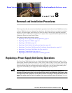
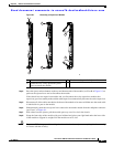
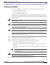
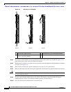
b. If the plastic protector shown in Figure 8-2 is included with the module, remove it by pulling it past
the back of the module. Keep the plastic protector and the other packing materials so that you can
easily ship the module at a later time.
Figure 8-2 Removing the Plastic Protector from the Supervisor Module
Caution To prevent ESD damage, avoid touching the electronic circuitry and prevent anything else from coming
in contact with the circuitry.
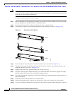
Step 12 On the replacement module, rotate both of the ejector levers away from the front of the module.
Step 13 If you are inserting the module into a Cisco Nexus 7010 chassis, rotate the module 90 degrees clockwise.
Step 14 Align the module to the chassis guides for the vacated slot (slot 5 or 6 on the Cisco Nexus 7010 chassis
or slot 9 or 10 on the Cisco Nexus 7018 chassis), and slide the module part way into the slot.
Step 15 With one or both hands on the front of the module, push the module all the way into the slot until it seats
on the midplane connector.
Step 16 Simultaneously push both ejector levers inward until they come in contact with the face of the module.
The module should be fully seated in the slot and the captive screws should be aligned with their holes
in the chassis. If there is another module to the right of the one that you are installing, the EMI gasket
should close the gap between the modules.
Step 17 Screw in the two captive screws to the chassis and tighten them to 69 N m (8 in-lbs).
Step 18 Reconnect the console cable to the CONSOLE SERIAL PORT as explained in the “Connecting to the
Console” section on page 5-2.
187888


Find Your Products By Category
Please Login
