

0
Owner's of the Cisco Systems Switch Cisco Nexus Switch gave it a score of 0 out of 5. Here's how the scores stacked up:

CHAPTER
Send document comments to nexus7k-docfeedback@cisco.com
8-1
Cisco Nexus 7000 Series Hardware Installation and Reference Guide
OL-18634-01
8
Removal and Installation Procedures
This chapter describes the removal and installation procedures for hte Cisco Nexus 7000 Series devices.
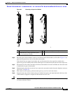
A Nexus 7000 Series device is designed for redundancy, which means that you can replace its modules,
fan trays, and power supply units if there is at least one other of the same type operating during the
replacement process. This chapter explains how to replace those components and the optional external
components (front door frame and air filter).
This chapter includes the following sections:
• Replacing a Power Supply Unit During Operations, page 8-1
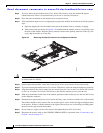
• Replacing a Supervisor Module, page 8-4
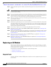
• Replacing an I/O Module, page 8-8
• Replacing a Fabric Module During System Operations, page 8-11
• Replacing a Cisco Nexus 7010 System Fan Tray During System Operations, page 8-13
• Replacing a Cisco Nexus 7010 Fabric Fan Tray, page 8-14
• Replacing a CompactFlash Card, page 8-15
• Replacing the Cisco Nexus 7010 System Air Filter, page 8-20
Replacing a Power Supply Unit During Operations
The Cisco Nexus 7000 Series devices use a load-balanced power supply that uses up to three or four
power supply units that each convert up to 1.2 kW, 3 kW, 3.5 kW, 6 kW, or 7.5 kW of AC power to DC
power for system operations. If you can set one power supply unit in standby mode and have the required
power load balanced by the remaining online power supply units, you can replace the standby power
supply unit with another power supply unit without interrupting system operations.
Warning
Blank faceplates and cover panels serve three important functions: they prevent exposure to
hazardous voltages and currents inside the chassis; they contain electromagnetic interference (EMI)
that might disrupt other equipment; and they direct the flow of cooling air through the chassis. Do not
operate the system unless all cards, faceplates, front covers, and rear covers are in place.
Statement
1029


Find Your Products By Category
Please Login
