

0
Owner's of the Cisco Systems Switch Cisco Nexus Switch gave it a score of 0 out of 5. Here's how the scores stacked up:
Send document comments to nexus7k-docfeedback@cisco.com
D-3
Cisco Nexus 7000 Series Hardware Installation and Reference Guide
OL-18634-01
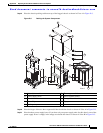
Appendix D Repacking the Cisco Nexus 7000 Series Device for Shipment
Repacking the System Components
Caution When you are handling the Cisco Nexus 7000 Series deivce or device components, you must follow the
ESD protocol at all times to prevent ESD damage. This protocol includes but is not limited to wearing
an ESD wrist strap that you connect to the earth ground in the data center building.
Repacking the Cisco Nexus 7010 Device
Caution Do not subject the pallet, system, or package to water or moisture.
To repack the Cisco Nexus 7010 system, follow these steps:
Step 1 Disconnect the system from the network and power it down as follows:
a. Power down the system by turning the power switch on each power supply to STBY.
b. Remove the power cables from the AC source and power supply.
c. Disconnect the cables that attach the Management and CMP processors on each supervisor module
to a console.
d. Disconnect the I/O cables from the I/O modules.
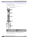
Step 2 If the chassis includes an optional air filter, remove it as follows:
a. On the lower left side and right side of the air filter, loosen the captive screw (one on each side) until
it no longer connects with the chassis.
b. On the upper left side and right side of the air filter, simultaneously pull out the two spring pins (one
on each side) and then pull the air filter away from the EMI frame and chassis.
Step 3 If the chassis includes the optional midframe doors, remove the doors and their frames as follows:
a. Remove each of the two front doors by loosening and removing the four screws that hold each door
frame to the chassis.
b. Remove the EMI frame, which holds the lower side frame pieces, by loosening the four captive
screws on the EMI frame until they no longer connect with the chassis.
c. Remove each of the two side frames from the EMI frame by loosening and removing the two screws
that hold each side frame piece to the EMI frame.
d. Reattach the EMI frame to the chassis by placing the EMI frame over the air intake area and aligning
its captive screws to their holes in the chassis. Securely tighten each of the captive screws.
e. Remove the bottom frame by loosening and removing the three screws on the frame.
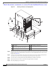
Step 4 Remove each power supply unit as follows:
a. Set out the power supply box and packaging materials.
b. Make sure that the power supply switch is set to standby (STBY).
c. Loosen the four captive screws on the front of the power supply unit until each screw is no longer
in contact with the chassis.
d. Grasp the power supply handle and pull the power supply unit part way out of the chassis.


Find Your Products By Category
Please Login
