

0
Owner's of the Cisco Systems Switch Cisco Nexus Switch gave it a score of 0 out of 5. Here's how the scores stacked up:
Send document comments to nexus7k-docfeedback@cisco.com
6-11
Cisco Nexus 7000 Series Hardware Installation and Reference Guide
OL-18634-01
Chapter 6 Managing the Device Hardware
Power Supply Configuration Modes
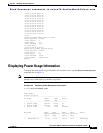
Note To display the current power supply configuration, use the show environment power command.
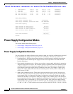
Power Supply Configuration Guidelines
Follow these guidelines when configuring power supply units:
• When power supply units with different capacities are installed in the switch, the amount of
available power differs based on one of the following configuration modes:
–
Combined mode—To activate this mode, use the power redundancy-mode combined
command. If the combined power provided by all of the installed power supply units meets the
power requirements of all of the device modules, then this mode is sufficient for running your
device.
For example, suppose your system has the following setup:
Power supply unit 1 outputs 6 kW.
The device power requirement is 8.784 kW.
The following two scenarios explain what happens for different numbers of power supply units
that you install:
Scenario 1: If you do not add a power supply unit, the available power (6 kW) is insufficient for
the device power requirement, so the device powers the supervisor modules, fabric modules, and
fan trays, before powering as many I/O modules as the remaining available power can support
(one or more I/O modules might not be powered).
Scenario 2: If you install an additional power supply unit that can output 3 kW, the available
power becomes 9.0
kW. The increased amount of available power exceeds the device power
requirement, so all of the modules and fan trays in the device can power up.
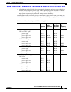
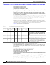
Table 6-3 shows the results for each scenario.
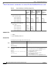
–
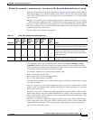
Power supply redundancy mode—To activate this power mode, use the
power
redundancy-mode ps-redundant command. The power supply unit that outputs the
most power provides the reserve power, and the combined output for the other power supply
units becomes the available power.
For example, suppose your system has the following setup:
Table 6-3 Combined Power Mode Scenarios
Scenario
Power
Supply 1
(kW)
Power
Supply 2
(kW)
System
Usage
(kW)
Available
Power
(kW) Result
1 6.0 — 8.784 6.0 Available power is less than system usage, so
you cannot power the entire system with this
mode.
2 6.0 3.0 8.784 9.0 Available power exceeds the system usage, so
you can use this mode to power your entire
system.


Find Your Products By Category
Please Login
