

0
Owner's of the Cisco Systems Switch Cisco Nexus Switch gave it a score of 0 out of 5. Here's how the scores stacked up:

Send document comments to nexus7k-docfeedback@cisco.com
7-5
Cisco Nexus 7000 Series Hardware Installation and Reference Guide
OL-18634-01
Chapter 7 Troubleshooting
Troubleshooting the I/O Modules
When you start up the device or install a new fabric module, the STATUS LED on the module is amber
while the module initializes. When the module becomes operational, the STATUS LED becomes green.
If an overtemperature condition occurs, the STATUS LED flashes red.
For a listing of the fabric module LEDs and the conditions that they indicate, see Table C-4 on page C-5.
To troubleshoot a fabric module hardware problem, follow these steps until the problem is resolved:
Step 1 Check if a STATUS LED is flashing red or is is unlit on each fabric module.
Step 2 Check if the power supply units are providing power to the chassis components. See the
“Troubleshooting the Power Supply” section on page 7-2.
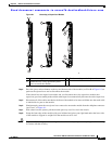
Step 3 Make sure that the fabric module is properly seated in the chassis as follows:
a. Loosen the captive screws on the fabric module until they are no longer in the chassis.
b. Press the eject buttons on either end of the module and simultaneously rotate out both ejector levers
until the module is unseated from the midplane.
c. Place one hand on the module handle and pull the module part way out of the chassis.
d. Push the module back into the chassis until it is seated on the midplane.
e. Simultaneously rotate both ejector levers until they both touch the front of the module. This action
fully seats the module on the midplane.
f. Make sure that each of the captive screws on the module is aligned with its holes in the chassis.
g. Screw in each captive screw to the chassis and tighten to 69 N m (8 in-lbs).
Step 4 Contact TAC for assistance (see the “Contacting Customer Service” section on page 7-6).
Troubleshooting the I/O Modules
The following conditions indicate that there are problems with one or more I/O modules:
• The IOM LED on the chassis is amber.
• The STATUS LED on an I/O module is red.
During initialization, the STATUS LED is amber while the I/O module powers up and performs
diagnostic tests. When the diagnostic tests are complete, the STATUS LED becomes green. If an
overtemperature condition occurs, the STATUS LED becomes amber. If the module is resetting, ejectors
are out, or there is a major overtemperature condition, the LED flashes red.
For a listing of the I/O module LEDs and the conditions that they indicate, see Table C-3 on page C-3.
To troubleshoot an I/O module hardware problem, follow these steps until the problem is resolved:
Step 1 Determine which I/O module has a problem. Check if a STATUS LED that is flashing red or is not lit on
a module.
Step 2 Check if the power supply units are providing power to the chassis components. See the
“Troubleshooting the Power Supply” section on page 7-2.
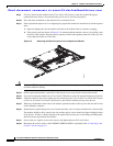
Step 3 Make sure that the I/O module is properly seated in the chassis by following these steps:
a. Loosen the captive screws on the I/O module until they are no longer in the chassis.
b. Press the eject buttons on either end of the module.
c. Simultaneously rotate out both ejector levers until the module is unseated from the midplane.


Find Your Products By Category
Please Login
