

0
Owner's of the Cisco Systems Switch Cisco Nexus Switch gave it a score of 0 out of 5. Here's how the scores stacked up:
Send document comments to nexus7k-docfeedback@cisco.com
A-4
Cisco Nexus 7000 Series Hardware Installation and Reference Guide
OL-18634-01
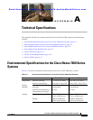
Appendix A Technical Specifications
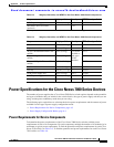
Power Specifications for the Cisco Nexus 7000 Series Devices
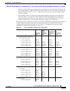
Power Supply Configuration Modes
You can configure one of the following power modes to either use the combined power provided by the
installed power supply units or to provide power redundancy when there is a power loss:
• Combined mode—Provides the maximum amount of available power by utilizing the combined
power output from all installed power supply units for device operations. This mode does not
provide redundancy.
• Power-supply redundancy mode—Allows you to replace a power supply during device operations.
All power supplies are active. The available power is calculated as the least amount of power
available from all but one of the power supply units (N+1). The reserve power is the amount of
power output by the power supply unit that can output the most power. For example, if three power
supply units output 3
kW, 6 kW, and 6 kW, the available power is 9 kW (3 kW + 6 kW) and the
reserve power is 6
kW.
• Input source redundancy mode—Takes power from two electrical grids so that if one grid goes
down, the other grid can provide the power needed by the device. Each grid powers half of each
power supply unit (grid A is connected to the Input 1 receptacle on each power supply unit and grid
B is connected to the Input 2 receptacle on each power supply unit). The available power is the
amount of power output by the portions of the power supply units that are connected to the same
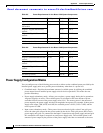
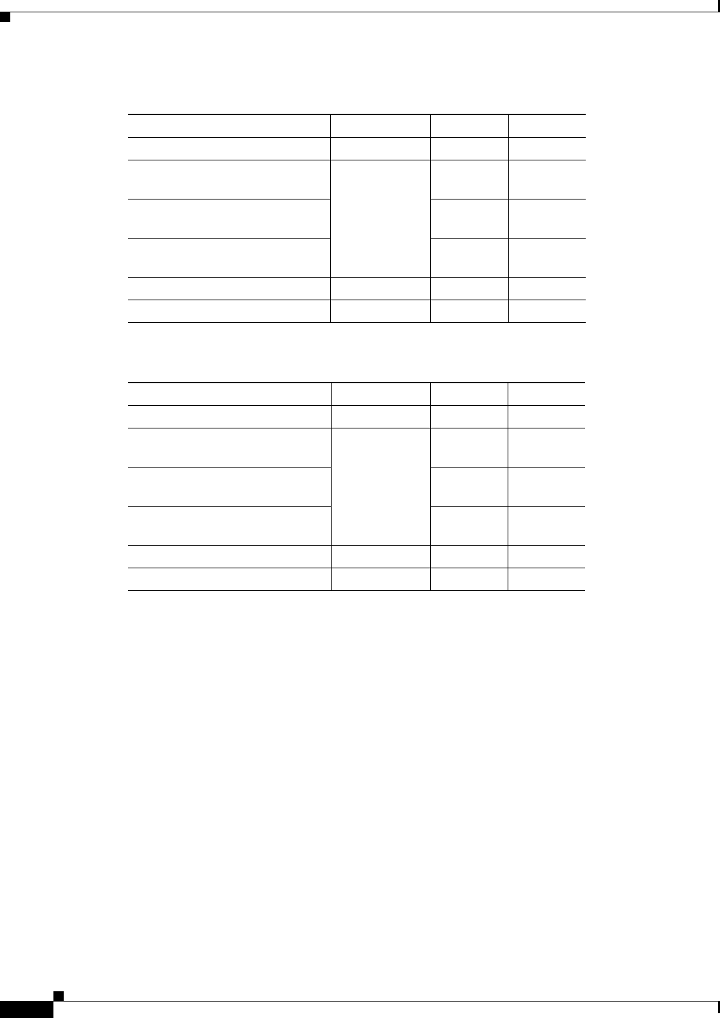
Table A-5 Power Requirements for the Nexus 7010 System Components
Component Quantity Maximum Typical
Supervisor module 2 210 W 190 W
48-port 10/100/1000-Ethernet
I/O module
1 to 8 400 W 358 W
48-port 1-Gigabit Ethernet I/O
module
400 W 358 W
32-port 10-Gigabit Ethernet I/O
module
750 W 611 W
Fabric module 3 to 5 60 W 55 W
All fan trays (total) — 2184 W 300 W
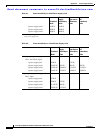
Table A-6 Power Requirements for the Nexus 7018 System Components
Component Quantity Maximum Typical
Supervisor module 2 210 W 190 W
48-port 10/100/1000 Ethernet I/O
module
1 to 16 400 W 358 W
48-port 1-Gigabit Ethernet I/O
module
400 W 358 W
32-port 10-Gigabit Ethernet I/O
module
750 W 611W
Fabric module 3 to 5 100 W 90 W
All fan trays (total) N.A. 1433 W 569 W


Find Your Products By Category
Please Login
