

0
Owner's of the Cisco Systems Switch Cisco Nexus Switch gave it a score of 0 out of 5. Here's how the scores stacked up:

CHAPTER
Send document comments to nexus7k-docfeedback@cisco.com
4-1
Cisco Nexus 7000 Series Hardware Installation and Reference Guide
OL-18634-01
4
Installing Power Supply Units
This chapter describes how to install power supply units in any Cisco Nexus 7000 Series chassis. This
chapter also explains how to connect the power supply to the AC power source. For information on
managing power modes, see the
“Power Supply Configuration Modes” section on page 6-8.
This chapter includes the following sections:
• Installing Power Supply Units, page 4-1
• Connecting the Power Supply Units to AC Power, page 4-2
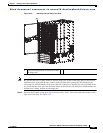
Installing Power Supply Units
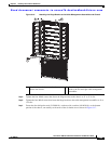
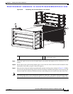
You can install two to three power supply units in the Cisco Nexus 7010 system and two to four power
supply units in the Cisco Nexus 7018 system. In either system, you must fill each power supply bay with
either a 6-kW or 7.5-kW power supply unit or cover the bay with a blank plate.
Caution Although each AC power interface on every power supply unit includes a ground connection, you should
also connect the chassis to an earth ground. For information on grounding the Nexus 7010 chassis, see
the
“Grounding the Cisco Nexus 7010 Chassis” section on page 2-11. For information on grounding the
Nexus 7018 chassis, see the “Grounding the Cisco Nexus 7018 Chassis” section on page 3-11.
After you install the chassis and connect the chassis to an earth ground, you can install the power supply
units.
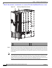
To install the power supply units, follow these steps for each 6-kW or 7.5-kW power supply unit:
Step 1 Ensure that the switch on the front of the power supply unit is in the STBY position and that the power
supply unit is not connected to AC power sources.
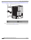
Step 2 Grasp the handle on the power supply unit with one hand, place the other hand under the unit, and orient
the unit to an open power supply bay on the rear of the chassis.
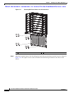
Step 3 Slide the unit all the way into the power supply bay until it is seated on the midplane and the four captive
screws on the front of the unit are aligned with their holes in the chassis.
Step 4 Secure each of the four capture screws into the chassis and tighten them to 69 N m (8 in-lbs).


Find Your Products By Category
Please Login
