

0
Owner's of the Cisco Systems Switch Cisco Nexus Switch gave it a score of 0 out of 5. Here's how the scores stacked up:
Send document comments to nexus7k-docfeedback@cisco.com
6-13
Cisco Nexus 7000 Series Hardware Installation and Reference Guide
OL-18634-01
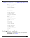
Chapter 6 Managing the Device Hardware
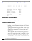
Power Supply Configuration Modes
Scenario 2: If you add a power supply that outputs 3 kW, the reserve power is 9 kW (3 kW for
three power supply units), and the available power is 6
kW (3 kW for each of two power supply
units). The available power does not meet the system usage requirement, so you cannot power
the entire device.
Scenario 3: If you add a power supply unit that outputs 7.5 kW, the reserve power is 9.75 kW
(3
kW for two power supply units and 3.75 kW for the new power supply unit), and the available
power is 9.75 kW (3
kW for two power supply units and 3.75 kW for the new power supply
unit). The available power exceeds the device usage requirement, so you can power up all of the
modules and fan trays in the device.
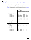
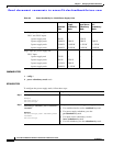
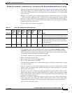
Table 6-5 shows the results for each scenario.
–
Full redundancy mode—To activate this power mode, use the power redundancy -mode
redundant command. The reserve power is the greater amount of reserve power for power
supply redundancy and input source redundancy, and the available power is the lesser amount
of available power for the same two redundancy modes.
For example, suppose your system has the following setup:
Grids A and B each provide 220 V.
Power supply units 1 and 2 each output 6.0 kW.
Device usage requirement is 8.784 kW.
Then the following three scenarios explain what happens for different numbers of power supply
units that you install:
Scenario 1: If you do not add a power supply unit, the reserve power is 6 kW and the available
power is 6
kW. The available power does not meet the device usage requirement, so you cannot
power up the entire device.
Scenario 2: If you add a 3-kW power supply unit, the reserve power is 9 kW (3 kW for three
power supply units on one grid), and the available power is 6
kW (3 kW for two power supply
units on a second grid). The available power does not meet the device usage requirement, so you
cannot power up the entire device.
Scenario 3: If you add a 6-kW power supply unit, the reserve power is 9 kW (3 kW for three
power supply units on the same grid), and the available power is 9
kW (3 kW for three power
supply units on a second grid). The available power meets the device usage requirements, so
you can power up the entire device.
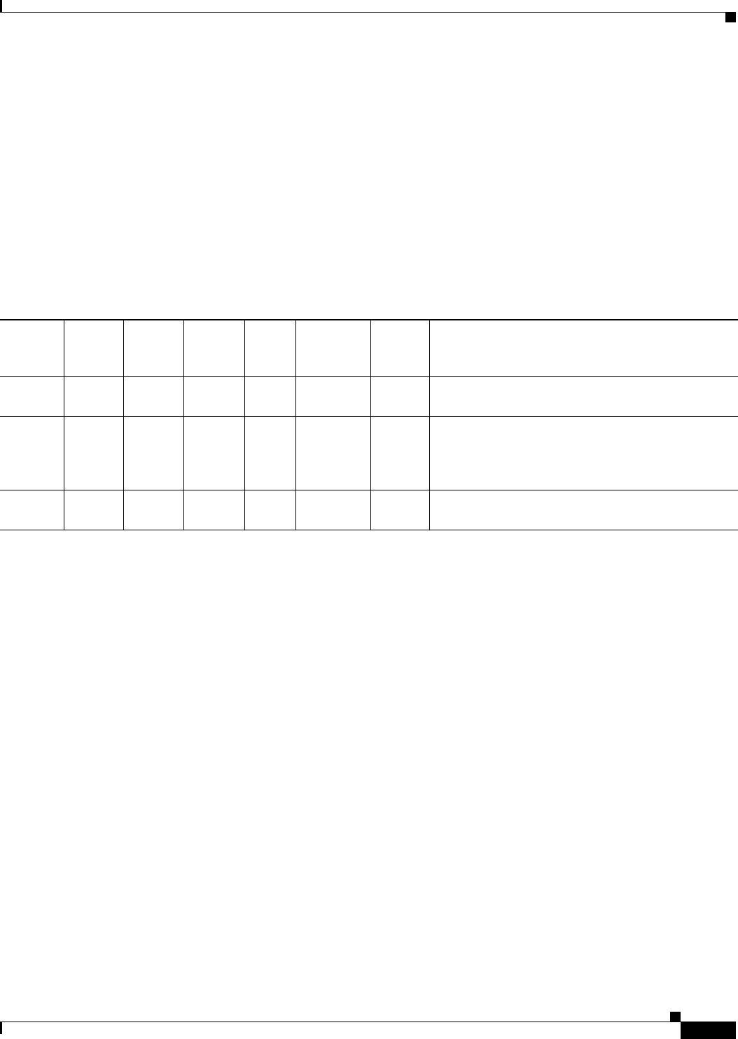
Table 6-5 Input Source Redundancy Mode Scenarios
Scenario
Power
Supply 1
(kW)
Power
Supply 2
(kW)
Power
Supply 3
(kW)
System
Usage
(kW)
Available
Power
(kW)
Reserve
Power
(kW)
Result
1 6.0 6.0 - 8.784 6.0 6.0 Available power (the power supply output for either
grid) does not meet the system usage requirement.
2 6.0 6.0 3.0 8.784 9.0 6.0 The power supply output for one grid meets the
system usage requirement, but the power supply
output for the other grid does not meet the system
usage requirement.
3 6.0 6.0 7.5 8.784 9.75 9.75 The power supply output for both grids meet the
meet the system usage requirement.


Find Your Products By Category
Please Login
