
0
Owner's of the Axis Communications Security Camera 2420 W/Lens gave it a score of 0 out of 5. Here's how the scores stacked up:


The Unit Connectors AXIS 2420 User’s Manual
64
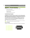
Appendix F - The Unit Connectors
This section provides an overview of the product connectors, namely:
•1 x RS-232 Serial Connector
•2 x I/O Connectors (I/O-A and I/O-B)
•1 x DC-Iris Connector
•1 x BNC Video Output
•1 x Ethernet network connector (RJ-45)
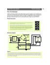
The RS-232 Serial Connector
In the absence of a local network connection, a single 9-pin D-sub connector provides a
dedicated physical interface for connecting a modem or computer to the AXIS 2420. This
RS-232 interface supports modem speeds of up to 115kbps and effectively allows the AXIS
2420 to operate as a standalone unit independent of any computer network. So, when a
local network connection is unavailable at the point of installation, you can simply
connect your PC to this connector and use the supplied Null Modem Cable to initially
configure your product. If you intend using the AXIS 2191 Audio Module with your
network camera, then this is the connector to use.
Note: The Axis Camera Division maintains a list of all supported modems. Please visit our Website at
www.axis.com for this and other late information on our products.
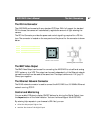
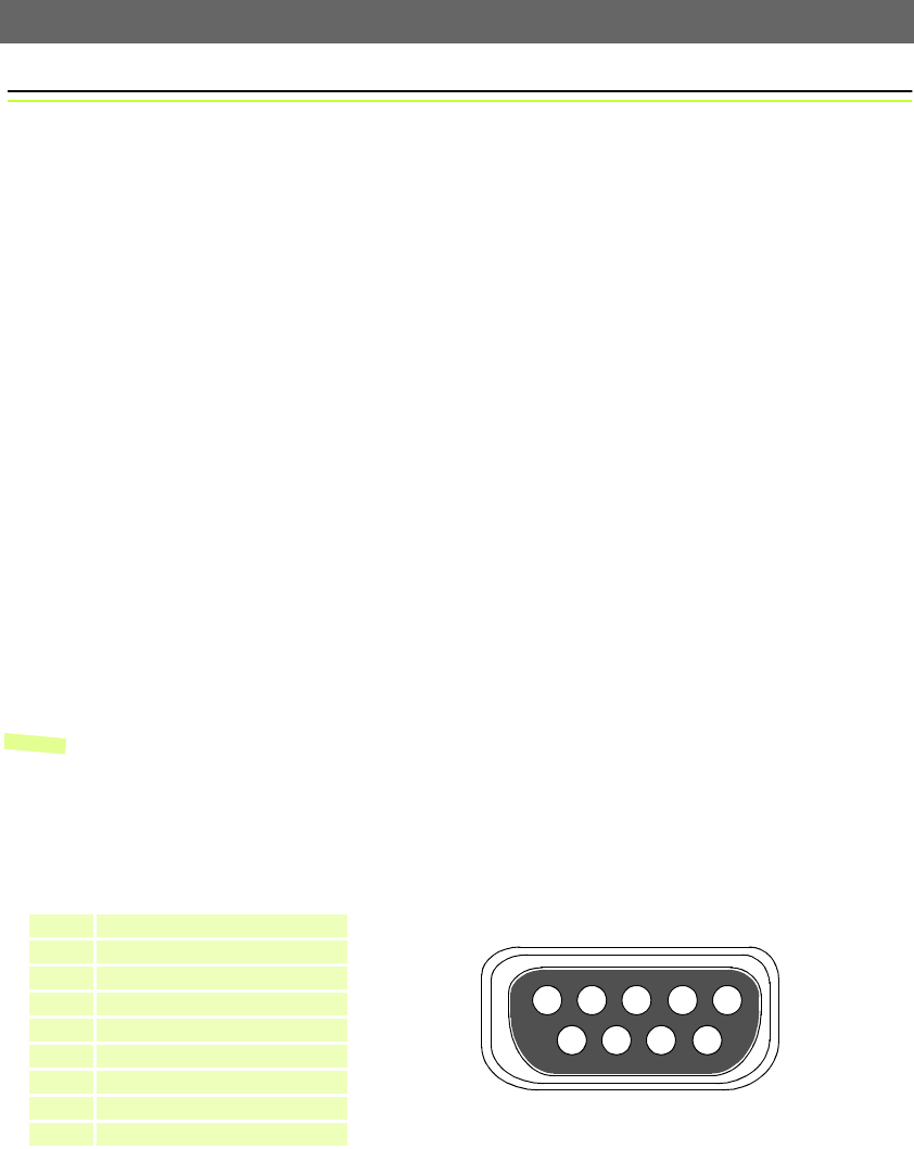
Pinout Information
A diagram of the RS-232 connector, complete with pinout information, is shown below.
Pin Function
1 CD (Carrier Detect)
2 RXD (Receive Data)
3 TXD (Transmit Data)
4 DTR (Data Terminal Ready)
5 GND (Ground)
6 DSR (Data Signal Ready)
7 RTS (Return To Send)
8 CTS (Clear To Send)
9 RI (Ring Indicator)
1
9
2
3
4
5
8
76


Find Your Products By Category
Please Login
