
0
Owner's of the Axis Communications Security Camera 2420 W/Lens gave it a score of 0 out of 5. Here's how the scores stacked up:
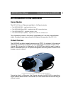
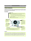
Physical Description AXIS 2420 User’s Manual
10
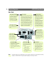
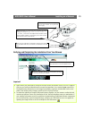
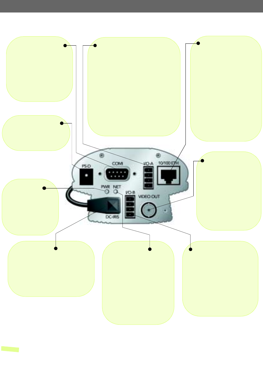
Rear Panel
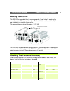
Note: The power supply for your AXIS 2420 is country-specific. Please refer to the Hardware Inventory
on page 11 and check that the type of power supply you are using is correct.
Power Supply Connector
PS-D connector for connec-
tion of the AXIS 2420 power
supply.
Power Indicator
Normally lit when
power is applied. If
not lit, or if flashing,
there is a problem with
the camera or with the
external power supply.
Network Indicator
After completion of the startup
and self-test routines, this
multi-colored indicator flashes
as follows:
• yellow - activity on a
10Mbps network
• green - activity on a
100Mbps network
• red - no connection with
the network
Network Connector
The AXIS 2420 is designed for
10 Mbps Ethernet and 100
Mbps Fast Ethernet networks
and connects to the network
via a twisted pair category 5
cable (10baseT and
100baseTX), terminated using
a standard RJ-45 connector.
Supporting NWAY, the AXIS
2420 detects the speed of the
local network segment and
varies the speed of data com-
munication accordingly (bet-
ween 10 Mbps and 100 Mbps).
I/O-A Connector
Provides the physical interface to a single
digital photo-coupled input that is used
for connecting a variety of external alarm
devices to the AXIS 2420, including tem-
perature sensors and switches. In combi-
nation with the configurable alarm
facilities, you can quickly develop a variety
of security applications that are triggered
on time- or alarm based- events. The con-
nector can also be utilized as an alterna-
tive connection point for DC power to or
from the unit. For pinout information, see
Appendix F - The Unit Connectors.
RS-232 Serial Connector
A single 9-pin D-sub connec-
tor provides the RS-232 serial
interface for connecting a
modem or the AXIS 2191
Audio Module. For pinout
information, refer to Appen-
dix F - The Unit Connectors.
DC-Iris Connector
Including full DC-Iris support, any
standard DC-Iris lens for outdoor
applications can be fitted.
The connector provides the power
and control signalling necessary for
a DC-Iris lens.
I/O-B Connector
Provides the physical interface for:
• 1 relay switch output - used
for the control of external
surveillance devices and ser-
vices; e.g. lighting annuncia-
tors, audible alarms, etc.
• RS-485/422 port for the con-
nection of pan tilt devices,
etc.
Video Out Connector
Via a standard BNC connec-
tor, this output allows the
AXIS 2420 to be connected
directly to traditional CCTV
systems. It can also be used
for adjusting the camera
focus in locations where you
are unable to view images on
a computer screen.


Find Your Products By Category
Please Login
