
0
Owner's of the 321 Studios Coffeemaker Oil Furnace gave it a score of 0 out of 5. Here's how the scores stacked up:

Manual 2100-422
Page 6
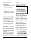
IMPORTANT
When a furnace is installed so that supply
ducts carry air circulated by the furnace to
areas outside the space containing the
furnace, the return air must also be handled
by a duct(s) sealed to the furnace casing and
terminating outside the space containing the
furnace This is to prevent drawing possible
hazardous combustion products into the
circulated air.
INSTALLING THE FURNACE
INSTRUMENTS REQUIRED FOR PROPER
SETUP OF THE FURNACE
It is important that a set of instruments capable of the
following requirements be used for the setup of this
furnace to ensure proper and safe operation:
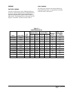
1. Oil pump pressure gauge that measures up to
150 PSI.
2. Smoke gun to pull smoke samples from flue.
3. Draft gauge that will measure -.02” water column
(W.C.)
4. Duct static pressure gauge 0-1.0” W.C. range.
5. Temperature gauge that can read from 50° F up to
700° F.
6. A gauge to measure CO
2
or O
2
.
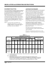
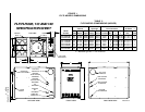
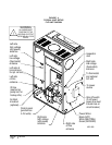
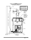
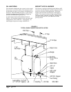
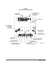
INSTALLATION
A typical installation is shown in Figures 4 and 5. All
parts of the furnace installation (furnace, oil tank and
piping systems, combustion and ventilation air, venting,
etc.) must comply with NFPA31, Installation of Oil
Burning Equipment -- latest edition. This drawing
shows the typical connecting parts needed to correctly
install this furnace. Make sure that all parts of the
heating system comply with the local codes.
Check the furnace and your load calculation to verify
that the unit is properly sized. (Refer to Equipment
Selection” section on Page 2.)
The correct size of unit needed may be substantially
smaller than the unit being replaced due to home
improvements and technology advancements since the
initial installation.
INADEQUATE SUPPLY AIR and/or RETURN
AIR DUCT SYSTEMS
Short cycling because of limit control operation can be
created by incorrectly designed or installed supply and/
or return air duct systems.
The duct systems must be designed using ASHRAE or
ACCA design manuals and the equipment CFM and
external static pressure ratings to insure proper air
delivery capabilities.
On replacement installations, particularly if equipment
is oversized, the duct systems can easily be undersized.
Modifications may be required to assure that the
equipment is operating within the approved
temperature rise range when under full rated input
conditions, and that no short cycling on limit controls is
occurring.
DUCT WORK
The air distribution system should be designed and
installed in conformance with manuals published by Air
Conditioning Contractors of America (ACCA) as set
forth in Manual D, or ASHRAE publications.
INSTALLING A COOLING UNIT
When the furnace is used in connection with a cooling
unit*, the furnace shall be installed parallel with or on
the upstream side of the cooling unit to avoid
condensation in the heating element. With a parallel
flow arrangement, the dampers or other means used to
control flow of air shall be adequate to prevent chilled
air from entering the furnace, and if manually operated,
must be equipped with means to prevent operation of
either unit, unless the damper is in the full heat or cool
position.
* A cooling unit is an air conditioning coil, heat
pump coil or chilled water coil.
When installing a cooling unit above an FH or FL
(below on an FC) series furnace, the coil must be
spaced far enough from the furnace outlet to assure
proper operation of the furnace. Bard supplied coils,
when used with Bard supplied coil cabinets, are
automatically positioned.
For top discharge FH and FL models, when coils are
installed without using Bard coil cabinets or coils of
another brand are used, the coil drain pan should be
located a minimum of two (2) inches above the top of
the furnace cabinet. If a greater clearance is specified
by the coil manufacturer then it would apply.
NOTE: IF DRAIN PAN IS ANYTHING OTHER
THAN A STEEL PAN PARTICULAR
ATTENTION MUST BE GIVEN TO THE
INSTALLATION INSTRUCTIONS FOR
THE COIL TO MAKE SURE IT IS
ACCEPTABLE FOR USE WITH THESE
OIL FURNACES HAVING MAXIMUM
OUTLET AIR TEMPERATURE OF 200° F.
See CFM versus static pressure curves on pages 33-36
for additional information.


Find Your Products By Category
Please Login
