
0
Owner's of the 321 Studios Coffeemaker Oil Furnace gave it a score of 0 out of 5. Here's how the scores stacked up:

Manual 2100-422
Page 25
LOUVERS AND GRILLES
In calculating free area for ventilation and combustion
air requirements, consideration shall be given to the
blocking effect of louvers, grilles, or screens protecting
openings. Screens used shall not be smaller than 1/4
inch (6.3 mm) mesh and shall be readily accessible for
cleaning. If the free area through a design of louver or
grille is known, it shall be used in calculating the size
opening required to provide the free area specified. If
the design and free area is not known, it may be
assumed that wood louvers will have 30-35 percent free
area and metal louvers and grilles will have 60-75
percent free area.
VENTING OPTIONS
This furnace is designed to be vented conventionally
into a vertical chimney or horizontally through a side
wall with an optional Field Controls side wall power
venting system.
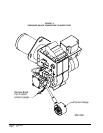
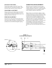
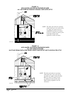
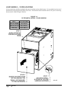
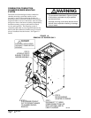
Note that the FH, FC and FLF series furnaces have been
designed to allow for bringing the vent system through
the cabinet side for increased venting flexibility. To
take advantage of this feature, simply remove the
desired knockout from either side or top of unit and
rotate flue box accordingly by removing four (4) screws
under cleanout plate as shown in Figure 4. Make sure
smoke pipe gasket is in place before reinstalling flue
box screws.
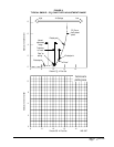
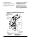
VERTICAL VENTING
If the unit is to be vertically vented make sure the flue
pipe from the furnace to the chimney is the same size
diameter as the flue outlet of the furnace which is 6”.
The flue pipe must have no reductions in diameter, be
made of a corrosion-resistant material having an
upward pitch of 1/4” for every foot of horizontal run,
and be made of material capable of handling
temperatures up to 1800° F.
A barometric damper is supplied with the furnace and
must be installed in the flue pipe observing the
instructions packaged with the damper control. The
barometric damper opening must be located in the same
atmospheric pressure zone as the combustion air inlet to
the furnace. The furnace must not be vented into the
same chimney with any solid fuel burning appliance
such as a wood burner or pellet burner. Masonry
chimneys must be lined with a listed system or other
approved material that will resist corrosion, softening or
cracking from flue gas temperatures up to 1800° F. See
Standard for Installation of Oil Burning Equipment
NFPA31 latest edition and Standard for Chimneys
NFPA211 latest edition for additional information.
HORIZONTAL VENTING
This furnace is designed to be horizontally vented
through a side wall with an optional side wall power
vent. The recommended side wall venter is the Field
Controls model number SWG-4HDS for 085 and 110
models, and SWG-5S for 140 models only. This venter
can be purchased through your local distributor. Follow
all installation instructions packaged with the venter
system.
THERMOSTAT
These furnaces are designed to be controlled with any
24V heating or heating/cooling thermostat. The
heat/cool thermostats must be designed for independent
heat/cool transformer circuits to assure that the 24V
transformer built into the oil primary control does not
conflict with the main furnace 24V transformer. The
heat anticipator should be set at 0.20A. This is a
nominal setting. The thermostat circuit should be
checked to verify setting.


Find Your Products By Category
Please Login
