
0
Owner's of the 321 Studios Coffeemaker Oil Furnace gave it a score of 0 out of 5. Here's how the scores stacked up:

Manual 2100-422
Page 15
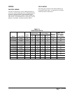
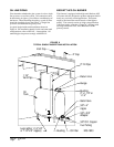
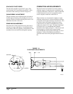
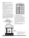
It should be located as close as possible to the
oil burner. Care should be taken to prevent air
leakage in the oil suction line. Use continuous
runs of copper tubing and use minimum
number of joints and fittings. Always use flare
fittings.
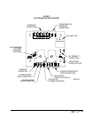
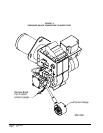
E. Adjustment of Electrodes Adjust ignition
electrodes as specified in Figure 10.
F. Operate Burner Operate burner, adjust air
setting for good flame by visual observation,
and run for at least 10 minutes or until
operation has stabilized.
G. Check Burner Pressure Bleed air from
pump and nozzle piping. Check pump pressure
and adjust to 100 psi, if necessary.
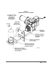
2. COMBUSTION ADJUSTMENT STEPS
H. Set Draft Check the draft reading over the
fire with a draft gauge through a hole in the
inspection door. The hole is above the flame
level. Adjust the barometric draft regulator on
the flue to give the over fire of -.02” W.C.
I. Check Smoke Readings After burner has
been operating 5 or 10 minutes, make a smoke
measurement in the flue, following the smoke
tester instructions. Oily or yellow smoke spots
on the filter paper are usually a sign of
unburned fuel, indicating very poor
combustion (and likely high emissions of
carbon monoxide and unburned hydrocarbons.)
This condition can sometimes be caused by too
much air, or by other factors. If this condition
cannot be corrected, major renovation or even
burner replacement may be necessary.
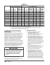
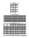
J. Develop Smoke - CO2 Curve Record
measurements of smoke and CO
2
from the
flue. Then establish the smoke - CO
2
curve by
taking readings over a range of air settings, as
shown in Figure 8.
To do this, start with the air gate set at nearly
full open and then take smoke and CO
2
readings at progressively lower air settings, as
necessary to visualize the general shape of the
curve. (The CO
2
readings will increase as the
air setting is decreased, unless combustion is
incomplete.) Do not set the air gate to give a
smoke reading above No. 4 or No. 5. Plot the
points on graph paper, as in Figure 8. Usually
3 or 4 readings are enough to establish the
curve.
In adjusting each air setting, it is helpful to
note the various positions of air gate at which
measurements are made so that the final setting
can be located quickly.
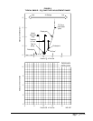
K. Adjust Air Setting Examine the smoke - CO
2
plot and, keeping in mind the curve of
Figure 6, note the location of the “knee” where
the smoke number begins to rise sharply.
Noting the air gate position marks, adjust the
air setting to a CO
2
level 1/2 to 1 percent lower
than the CO
2
level at the “knee”. (This
provides a tolerance against possible shifts in
the setting over a period of time.) Do not
increase the air setting any more than necessary
on the lower portion of the curve below the
“knee”
The characteristic curve for some burners may
not yield a distinct “knee” in the curve. In such
cases, the setting should be made near the
minimum smoke, (using judgement).
Lock the air adjustment and repeat draft,
CO
2
and smoke measurements to make sure
the setting has not shifted.
3. COMBUSTION DIAGNOSIS
L. Check Performance A well-matched and
well-tuned burner should be capable of
operation with smoke not greater than No. 2
and at a CO
2
level not less than 10%.
If this cannot be reached, check the following:
1. Air leaks into the combustion chamber or
heat exchanger can dilute the combustion
gases and prevent normal CO
2
readings.
Such leaks should be sealed with furnace
cement or other high-temperature sealant.
To check for dilution by leakage, measure
the CO
2
at as high a point as possible over
the fire, using a stainless steel tube
inserted through the fire door sample hole
(as described earlier for overfire draft
measurements), and compare this with the
CO
2
measured in the flue. A difference of
more than 1 percent CO
2
between the flue
and overfire reading usually indicates air
entry through leaks that have not been
properly sealed.
Seal between the probe and inspection door
sample hole during test. The inspection
door hole should be sealed when not being
used to avoid leakage of air through it.
(See Step H.)
2. If the CO
2
level of 10% cannot be reached
without exceeding No. 2 smoke, poor
mixing of air and fuel is likely.
It may be necessary to replace the
combustion head or try different settings.


Find Your Products By Category
Please Login
