

0
Owner's of the 321 Studios Coffeemaker Oil Furnace gave it a score of 0 out of 5. Here's how the scores stacked up:
Manual 2100-422
Page 20
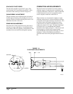
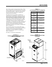
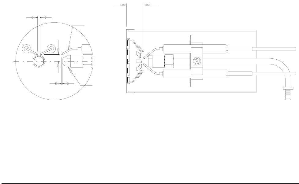
SPACING OF ELECTRODES
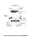
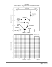
The electrodes should be spaced 5/32” apart. They
should extend 1/16” beyond the end and 5/16” above
the center of the nozzle tip as shown in Figure 10.
GUN ASSEMBLY ADJUSTMENT
The gun assembly can be adjusted in the slot inside of
fan housing by loosening screw holding slot cover in
position. Nozzle tip should ordinarily be located 1-1/8”
behind the front face of the cone.
REMOVING GUN ASSEMBLY
Disconnect the oil line at the fan housing and remove
lock nuts on copper tube fitting. Loosen igniter hold
down clamps, then swing igniter up and backward. Gun
assembly can now be removed through this opening.
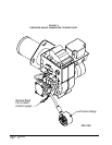
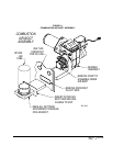
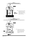
COMBUSTION AIR REQUIREMENTS
This furnace must be installed in a location where a
sufficient supply of combustion air is available for the
complete combustion of the fuel oil. Keep in mind that
a certain amount of excess air is required as well to
ensure complete combustion of the fuel oil.
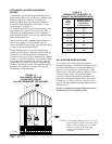
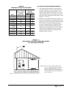
When structures are constructed too tightly to supply
sufficient combustion air, air from outside the structure
is required to be brought in directly to the furnace. This
furnace has been conveniently designed to accept a
combustion air boot which is attached directly to the
outdoors by means of a 4” pipe. This pipe can be rigid
or flexible, but it is recommended that a metallic
material be used. Refer to Figure 11. The air boot used
for this design is a Field Controls model number
CAS-2B-90E that can be purchased through your local
distributor. Follow all installation procedures as
specified in the instructions packaged with the air boot
kit.
FIGURE 10
ELECTRODE ADJUSTMENTS
MIS-160
5/32 GAP
1-1/8
5/16
1/16
NOZZLE


Find Your Products By Category
Please Login
