
0
Owner's of the 321 Studios Coffeemaker Oil Furnace gave it a score of 0 out of 5. Here's how the scores stacked up:
Manual 2100-422
Page 14
BURNER SETUP AND ADJUSTMENT
PROCEDURES
All oil burner installations should be performed by a
qualified installer in accordance with regulations of the
National Fire Protection Standard for Oil-Burning
Equipment, NFPA31 -- latest edition, and in complete
compliance with all local codes and authorities having
jurisdiction. A qualified installer is an individual or
agency who is responsible for the installation and
adjustments of the heating equipment and who is
properly licensed and experienced to install oil-burning
equipment in accordance with all codes and ordinances.
The proper installation and adjustment of any oil burner
requires technical knowledge and the use of combustion
test instruments. The following procedure must be
followed to correctly adjust the burner to match the
specific characteristics of the installation.
IMPORTANT
Always use combustion test instruments when
making burner adjustments and draft gauge
when setting the barometric damper. It is
virtually impossible to make accurate and
reliable adjustments using the “eyeball”
method.
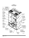
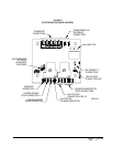
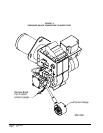
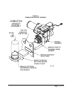
Check all oil lines and connections for leaks.
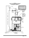
Connect pressure gauge by removing bleed fitting and
screwing in pressure gauge. See Figure 9.
1. PREPARATION STEPS
A. Calibrate and Check Operation of
Measuring Equipment Follow
manufacturer’s recommended procedures for
calibration and equipment check out.
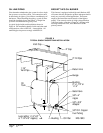
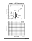
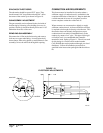
B. Prepare Heating Unit for Testing Drill two
1/4 inch holes in the flue between the heating
plant and the barometric draft regulator. If
space permits, the holes should be located in a
straight section of the flue, at least two flue
diameters from the elbow in the flue pipe and at
least one diameter from the draft regulator. The
purpose of the two holes in the flue pipe is to
speed up testing and reduce instrument
handling.
C. Clean and Seal Heating Plant Make sure the
burner blast tube, fan housing, and blower
wheel are clear of dirt and lint. Seal any air
leaks into the combustion chamber.
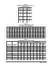
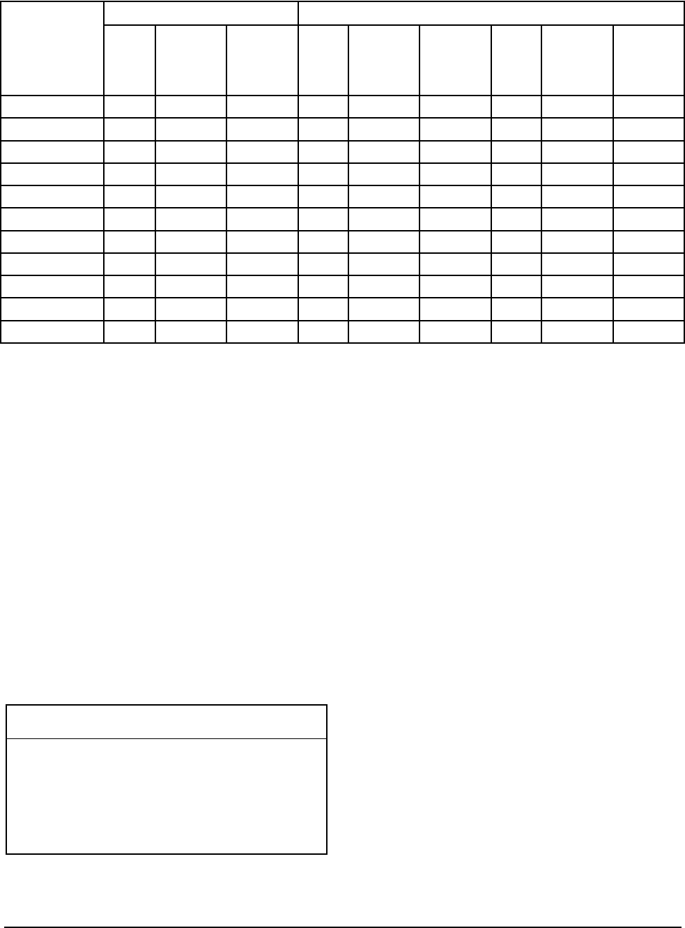
D. Nozzle Inspection Annual replacement of
nozzle is recommended. The nozzle size
should match the design load . DO NOT
OVERSIZE. (Determination of oversizing can
be determined prior to your adjustment. If the
firing rate should be reduced refer to Table 4.)
Short cycles and low percent :on: time result in
higher overall pollutant emissions and lower
thermal efficiency. An in-line oil filter will
reduce service problems due to nozzle clogging.
j
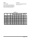
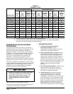
70 degree hollow cone spray pattern, 100 PSIG pump pressure
k
Annual fuel utilization efficiency and heating capacity based upon U.S. Government standard
test using D.O.E. isolated combustion rating procedure.
TABLE 4
FURNACE DATA
rebmuNledoM
dradnatSdellatsnIecanruFnoitpOdellatsnIdleiF
s
1
elzzoN
eziS
tupnI
HUTB
2
gnitaeH
yticapaC
HUTB
1
elzzoN
eziS
tupnI
HUTB
2
gnitaeH
yticapaC
HUTB
1
elzzoN
eziS
tupnI
HUTB
2
gnitaeH
yticapaC
HUTB
E63D580FLF57.000,501000,5856.000,19000,4755.000,77000,36
E63D580RLF57.000,501000,5856.000,19000,4755.000,77000,36
E84D011FLF00.1000,041000,31158.000,911000,69ANANAN
E84D011RLF00.1000,041000,31158.000,911000,69ANANAN
E06D011FLF00.1000,041000,31158.000,911000,69ANANAN
E06D011RLF00.1000,041000,31158.000,911000,69ANANAN
E06D041RLF52.1000,571000,24101.1000,451000,521ANANAN
E63D580CF57.000,501000,5856.000,19000,4755.000,77000,36
E63D580HF57.000,501000,5856.000,19000,4755.000,77000,36
E84D011HF00.1000,041000,31158.000,911000,69ANANAN
E06D011HF00.1000,041000,31158.000,911000,69ANANAN


Find Your Products By Category
Please Login
