
0
Owner's of the DeWalt Saw Double Bevel Sliding Compound Miter Saw gave it a score of 0 out of 5. Here's how the scores stacked up:
PRETESTING WITH SCRAP MATERIAL IS EXTREMELY IMPORTANT!
INSTRUCTIONS FOR CUTTING CROWN MOLDING LAYING FLAT AND USING THE
COMPOUND FEATURES
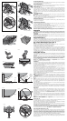
1. Molding should lay flat with broad back surface down on saw table (Fig. 17).
2. Top of molding against fence.
3. The settings below are for all standard (U.S.) crown molding with 52° and 38° angles.
INSIDE CORNER OUTSIDE CORNER
Left side
Bevel left 33.9°
Miter table set at right 31.62°
Save left end of cut
Bevel right 33.9°
Miter table set at left 31.62°
Save left end of cut
Right side
Bevel right 33.9°
Miter table set at left 31.62°
Save right end of cut
Bevel left 33.9°
Miter table set at right 31.62°
Save right end of cut
When setting bevel and miter angles for all compound miters, remember that:
The angles presented for crown moldings are very precise and difficult to set exactly. Since they
can easily shift slightly and very few rooms have exactly square corners, all settings should be
tested on scrap molding.
PRETESTING WITH SCRAP MATERIAL IS EXTREMELY IMPORTANT!
ALTERNATIVE METHOD FOR CUTTING CROWN MOLDING
Place the molding on the table at an angle between the fence and the saw table, as shown in
Figure 18. Use of the crown molding fence accessory (DW7084) is highly recommended because
of its degree of accuracy and convenience (Fig. 1). The crown molding fence accessory is
available for purchase from your local dealer.
The advantage to cutting crown molding using this method is that no bevel cut is required. Minute
changes in the miter angle can be made without affecting the bevel angle. This way, when corners
other than 90º are encountered, the saw can be quickly and easily adjusted for them. Use the
crown molding fence accessory to maintain the angle at which the molding will be on the wall.
INSTRUCTIONS FOR CUTTING CROWN MOLDING ANGLED BETWEEN THE FENCE
AND BASE OF THE SAW FOR ALL CUTS
1. Angle the molding so the bottom of the molding (part which goes against the wall when
installed) is against the fence and the top of the molding is resting on the saw table, as shown
in Figure 18.
2. The angled “flats” on the back of the molding must rest squarely on the fence and saw table.
INSIDE CORNER OUTSIDE CORNER
Left side
Miter right at 45°
Save right side of cut
Miter left at 45°
Save right side of cut
Right side
Miter left at 45°
Save left side of cut
Miter right at 45°
Save left side of cut
Special Cuts
NEVER MAKE ANY CUT UNLESS THE MATERIAL IS SECURED ON THE TABLE AND
AGAINST THE FENCE.
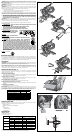
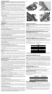
ALUMINUM CUTTING (FIG. 19, 20)
ALWAYS USE THE APPROPRIATE SAW BLADE MADE ESPECIALLY FOR CUTTING ALUMINUM.
These are available at your local D
EWALT retailer or DEWALT service center. Certain workpieces,
due to their size, shape or surface finish, may require the use of a clamp or fixture to prevent
movement during the cut. Position the material so that you will be cutting the thinnest cross section,
as shown in Figure 19. Figure 20 illustrates the wrong way to cut these extrusions.
Use a stick wax cutting lubricant when cutting aluminum. Apply the stick wax cutting lubricant
directly to the saw blade before cutting. Never apply stick wax to a moving blade. The wax,
available at most hardware stores and industrial mill supply houses, provides proper lubrication and
keeps chips from adhering to the blade.
Be sure to properly secure workpiece.
Refer to Saw Blades under Optional Accessories for correct saw blade.
BOWED MATERIAL (FIG. 21, 22)
When cutting bowed material always position it as shown in Figure 21 and never like that shown in
Figure 22. Positioning the material incorrectly will cause it to pinch the blade near the completion
of the cut.
CUTTING PLASTIC PIPE OR OTHER ROUND MATERIAL
Plastic pipe can be easily cut with your saw. It should be cut just like wood and CLAMPED OR
HELD FIRMLY TO THE FENCE TO KEEP IT FROM ROLLING. This is extremely important
when making angle cuts.
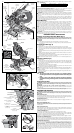
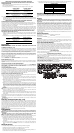
CUTTING LARGE MATERIAL (FIG. 23)
Occasionally you will encounter a piece of wood a little too large to fit beneath the lower guard. If
this occurs, simply place your right thumb on the upper side of the guard and roll the guard up
just enough to clear the workpiece, as shown in Figure 23. Avoid doing this as much as possible,
but if need be, the saw will operate properly and make the bigger cut. NEVER TIE, TAPE, OR
OTHERWISE HOLD THE GUARD OPEN WHEN OPERATING THIS SAW.
SPECIAL SET-UP FOR WIDE CROSSCUTS (FIG. 24, 25)
Your saw can cut very wide (up to 16.1" [409 mm]) workpieces when a special set-up is used. To
set the saw up for these workpieces, follow these steps:
1. Remove both left and right sliding fences from the saw and set aside. To remove them,
unscrew the fence adjustment knobs several turns and slide each fence outward. Adjust and
lock the miter control so that it is at 0º miter.
2. Make a platform using a piece of 1.5" (38 mm) thick particleboard or similar flat strong 1.5" thick
wood to the dimensions: 14.5" x 26" (368 x 660 mm). The platform must be flat, otherwise the
material could move during cutting and cause injury.
3. Mount the 14.5" x 26" (368 x 660 mm) platform to the saw using four 3" (76.2 mm) long wood
screws through the holes in the base fence (Fig. 24). Four screws must be used to properly
secure the material. When the special set-up is used, the platform will be cut into two pieces.
Ensure the screws are tightened properly, otherwise material could loosen and cause injury.
Ensure the platform is firmly flat on the table, against the fence, and centered evenly from left
to right.
WARNING: Ensure the saw is mounted firmly to a stable flat surface. Failure to do so could
cause the saw to be unstable and fall causing personal injury.
4. Place the workpiece to be cut on top of the platform mounted to the table. Ensure the
workpiece is firmly against the back of the base fence (Fig. 25).
5. Secure the material before cutting. Cut slowly through the material using a out-down-and-back
motion. Failure to clamp securely or cut slowly could result in the material coming loose and
causing injury.
After several cuts are made at various miter angles other than 0º, the platform may weaken and not
properly support the work. Install a new, unused platform to the saw after presetting the desired
miter angle.
CAUTION: Continued use of a platform with several kerfs may cause loss of material control
and possible injury.
Removing and Replacing Belt (Fig. 4, 26)
The belt is designed to last the life of the tool. However, abuse of the tool could cause the belt to fail.
If the blade does not turn when the motor is running, the belt has failed. To inspect or replace the
belt, remove the belt cover screws. Remove the belt cover. Inspect the ribs of the belt for wear or
failure. Check belt tension by squeezing the belt as shown in Figure 26. The belt halves should
almost touch when squeezing firmly with the thumb and index finger. To adjust the tension, loosen,
but do not remove, the four crosshead screws shown. Then rotate the set screw on the top of
the motor plate casting until the proper tension is achieved. Tighten the four screws securely and
replace the belt cover.
NOTICE: Overtightening the belt will cause premature motor failure.
MAINTENANCE
WARNING: To reduce the risk of serious personal injury, turn off the tool and disconnect
it from the power source before attempting to move it, change accessories or make any
adjustments.
WARNING: To reduce the risk of serious personal injury, DO NOT touch the sharp
points on the blade with fingers or hands while performing any maintenance.
DO NOT use lubricants or cleaners (particularly spray or aerosol) in the vicinity of the plastic guard.
The polycarbonate material used in the guard is subject to attack by certain chemicals.
• All bearings are sealed. They are lubricated for life and need no further maintenance.
• Periodically clean all dust and wood chips from around AND UNDER the base and the
rotary table. Even though slots are provided to allow debris to pass through, some dust will
accumulate.
• The brushes are designed to give you several years of use. If they ever need replacement
follow the instructions under Brushes or return the tool to the nearest service center for
repair.
Worklight Cleaning
For the best worklight performance, perform the following maintenance regularly.
• Carefully clean sawdust and debris from worklight lens with a cotton swab.
• DO NOT use solvents of any kind, they may damage the lens.
• Dust build-up can block the worklight and prevent it from accurately indicating the line of cut.
• Follow miter saw’s instruction manual to remove and install blade.
• With blade removed from saw, clean pitch and build-up from blade. Pitch and debris can
interfere with the worklight and prevent it from accurately indicating the line of cut.
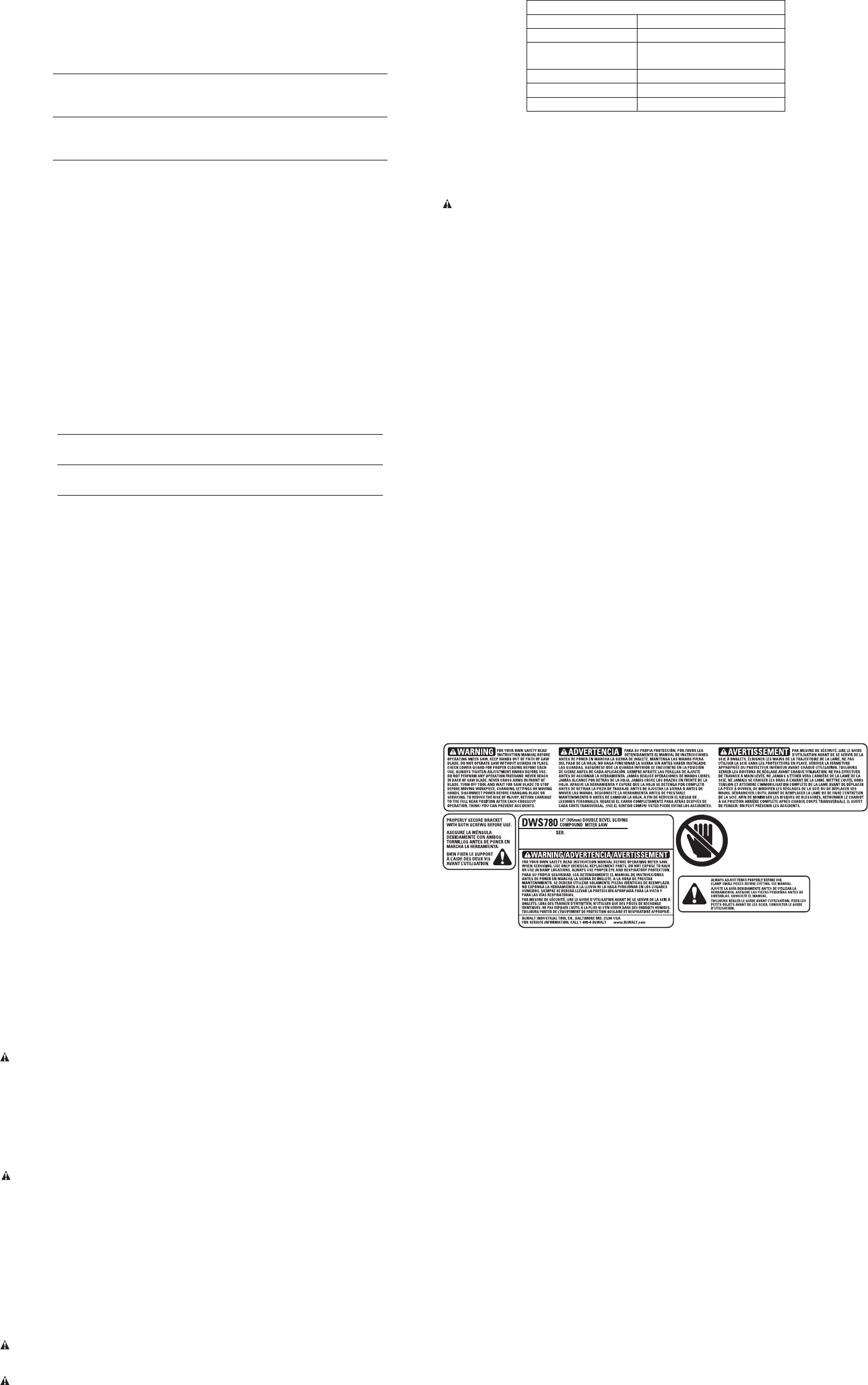
SPECIFICATIONS
Light source Power LED
Worklight 3.3 V DC
Power Supply Input: 120–240 V AC; 50/60Hz
Output: 5 V DC; 0.45 A
Operating Temperature 14°F to 104°F (-10°C to 40°C)
Storage Temperature -22°F to 176°F (-30°C to 80°C)
Environmental Water resistant
Dust Duct Cleaning
Depending on your cutting environment, saw dust can clog the dust duct and may prevent dust
from flowing away from the cutting area properly. With the saw unplugged and the saw head raised
fully, low pressure air or a large diameter dowel rod can be used to clear the dust out of the dust
duct.
Brushes
WARNING: To reduce the risk of serious personal injury, turn off the tool and disconnect
it from the power source before attempting to move it, change accessories or make any
adjustments.
Inspect carbon brushes regularly by unplugging tool, removing the motor endcap (Fig. 4), lifting
the brush spring and withdrawing the brush assembly. Keep brushes clean and sliding freely in
their guides. Always replace a used brush in the same orientation in the holder as it was prior to
its removal. If the brushes are worn down to approximately 1/2" (12.7 mm), the springs will no
longer exert pressure and they must be replaced. Use only identical D
EWALT brushes. Use of the
correct grade of brush is essential for proper operation of electric brake. New brush assemblies
are available at D
EWALT service centers. The tool should be allowed to “run in” (run at no load) for
10 minutes before use to seat new brushes. The electric brake may be erratic in operation until the
brushes are properly seated (worn in). Always replace the brush inspection cap after inspection or
servicing the brushes.
While “running in” DO NOT TIE, TAPE, OR OTHER WISE LOCK THE TRIGGER SWITCH ON. HOLD
BY HAND ONLY.
Service Information
Please have the following information available for all service calls:
Model Number __________________ Serial Number _____________________________________
Date and Place of Purchase __________________________________________________________
Repairs
To assure product SAFETY and RELIABILITY, repairs, maintenance and adjustment should be
performed by a D
EWALT factory service center, a DEWALT authorized service center or other
qualified service personnel. Always use identical replacement parts.
Three Year Limited Warranty
DEWALT will repair, without charge, any defects due to faulty materials or workmanship for three
years from the date of purchase. This warranty does not cover part failure due to normal wear or tool
abuse. For further detail of warranty coverage and warranty repair information, visit www.dewalt.
com or call 1-800-4-D
EWALT (1-800-433-9258). This warranty does not apply to accessories or
damage caused where repairs have been made or attempted by others. This warranty gives you
specific legal rights and you may have other rights which vary in certain states or provinces. In
addition to the warranty, D
EWALT tools are covered by our:
1 YEAR FREE SERVICE
D
EWALT will maintain the tool and replace worn parts caused by normal use, for free, any time
during the first year after purchase.
90 DAY MONEY BACK GUARANTEE
If you are not completely satisfied with the performance of your D
EWALT Power Tool, Laser, or
Nailer for any reason, you can return it within 90 days from the date of purchase with a receipt for
a full refund – no questions asked.
LATIN AMERICA: This warranty does not apply to products sold in Latin America. For products
sold in Latin America, see country specific warranty information contained either in the packaging,
call the local company or see website for warranty information.
FREE WARNING LABEL REPLACEMENT: If your warning labels become illegible or are missing,
call 1-800-4-D
EWALT (1-800-433-9258) for a free replacement.


Find Your Products By Category
Please Login
