
0
Owner's of the DeWalt Saw Double Bevel Sliding Compound Miter Saw gave it a score of 0 out of 5. Here's how the scores stacked up:
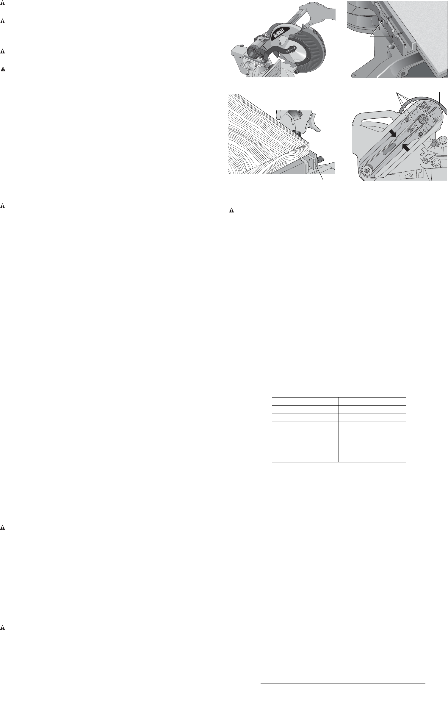
CLAMPING THE WORKPIECE
WARNING: To reduce the risk of serious personal injury, turn off the tool and disconnect
it from the power source before attempting to move it, change accessories or make any
adjustments.
WARNING: A workpiece that is clamped, balanced and secure before a cut may become
unbalanced after a cut is completed. An unbalanced load may tip the saw or anything the saw is
attached to, such as a table or workbench. When making a cut that may become unbalanced,
properly support the workpiece and ensure the saw is firmly bolted to a stable surface. Personal
injury may occur.
WARNING: The clamp foot must remain clamped above the base of the saw whenever the
clamp is used. Always clamp the workpiece to the base of the saw – not to any other part of the
work area. Ensure the clamp foot is not clamped on the edge of the base of the saw.
CAUTION: Always use a work clamp to maintain control and reduce the risk of workpiece
damage and personal injury, if your hands are required to be within 6" of the blade during the cut.
If you cannot secure the workpiece on the table and against the fence by hand (irregular shape,
etc.), or your hand would be less than 6" (152 mm) from the blade, a clamp or other fixture must
be used.
Use the material clamp provided with your saw. To purchase the material clamp, contact your local
retailer or D
EWALT service center.
Other aids such as spring clamps, bar clamps or C-clamps may be appropriate for certain sizes
and shapes of material. Use care in selecting and placing these clamps. Take time to make a dry
run before making the cut. The left or right fence will slide from side to side to aid in clamping.
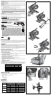
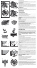
TO INSTALL CLAMP
1. Insert it into the hole behind the fence. The clamp should be facing toward the back of the miter
saw. The groove on the clamp rod should be fully inserted into the base. Ensure this groove is
fully inserted into the base of the miter saw. If the groove is visible, the clamp will not be secure.
2. Rotate the clamp 180º toward the front of the miter saw.
3. Loosen the knob to adjust the clamp up or down, then use the fine adjust knob to firmly clamp
the workpiece.
NOTE: Place the clamp on the opposite side of the base when beveling. ALWAYS MAKE DRY
RUNS (UNPOWERED) BEFORE FINISH CUTS TO CHECK THE PATH OF THE BLADE. ENSURE
THE CLAMP DOES NOT INTERFERE WITH THE ACTION OF THE SAW OR GUARDS.
Adjustments
WARNING: To reduce the risk of serious personal injury, turn off the tool and disconnect
it from the power source before attempting to move it, change accessories or make any
adjustments.
Your miter saw is fully and accurately adjusted at the factory at the time of manufacture. If
readjustment due to shipping and handling or any other reason is required, follow the instructions
below to adjust your saw.
Once made, these adjustments should remain accurate. Take a little time now to follow these
directions carefully to maintain the accuracy of which your saw is capable.
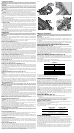
MITER SCALE ADJUSTMENT (FIG. 5, 10)
Unlock the miter lock handle and swing the miter arm until the miter latch button locks it at the
0° miter position. Do not lock the miter lock handle. Place a square against the saw’s fence and
blade, as shown. (Do not touch the tips of the blade teeth with the square. To do so will cause an
inaccurate measure ment.) If the saw blade is not exactly perpendicular to the fence, loosen the four
screws that hold the miter scale and move the miter lock handle and the scale left or right until the
blade is perpendicular to the fence, as measured with the square. Retighten the four screws. Pay
no attention to the reading of the miter pointer at this time.
MITER POINTER ADJUSTMENT (FIG. 5)
Unlock the miter lock handle to move the miter arm to the zero position. With the miter lock handle
unlocked, allow the miter latch to snap into place as you rotate the miter arm to zero. Observe the
miter pointer and miter scale shown in Figure 5. If the pointer does not indicate exactly zero, loosen
the miter pointer screw holding the pointer in place, reposition the pointer and tighten the screw.
BEVEL SQUARE TO TABLE ADJUSTMENT (FIG. 4, 6, 11)
To align the blade square to the table, lock the arm in the down position with the lock down pin.
Place a square against the blade, ensuring the square is not on top of a tooth. Loosen the bevel
lock knob and ensure the arm is firmly against the 0° bevel stop. Rotate the 0° bevel adjustment
screw with the 1/2" (13 mm) blade wrench as necessary so that the blade is at 0° bevel to the table.
BEVEL POINTERS (FIG. 6)
If the bevel pointers do not indicate zero, loosen each screw that holds each bevel pointer in place
and move them as necessary. Ensure the 0° bevel is correct and the bevel pointers are set before
adjusting any other bevel angle screws.
BEVEL STOP 45º RIGHT AND LEFT ADJUSTMENT (FIG. 4, 6)
To adjust the right 45° bevel angle, loosen the bevel lock knob and pull the 0° bevel stop to override
the 0° bevel stop. When the saw is fully to the right, if the bevel pointer does not indicate exactly
45°, turn the left 45° bevel adjustment screw with the 1/2" (13 mm) blade wrench until the bevel
pointer indicates 45°.
To adjust the left 45° bevel stop, first loosen the bevel lock knob and tilt the head to the left. If the
bevel pointer does not indicate exactly 45°, turn the right 45° bevel adjustment screw until the bevel
pointer reads 45°.
ADJUSTING THE BEVEL STOP TO 22.5° (OR 33.86°) (FIG. 4, 6)
NOTE: Adjust the bevel angles only after performing the 0° bevel angle and bevel pointer
adjustment.
To set the left 22.5° bevel angle, flip out the left 22.5° bevel pawl. Loosen the bevel lock knob and
tilt the head fully to the left. If the bevel pointer does not indicate exactly 22.5°, turn the crown
adjustment screw contacting the pawl with a 7/16" (10 mm) wrench until the bevel pointer reads
22.5°.
To adjust the right 22.5° bevel angle, flip out the right 22.5° bevel pawl. Loosen the bevel lock knob
and pull the 0° bevel stop to override the 0° bevel stop. When the saw is fully to the right, if the
bevel pointer does not indicate exactly 22.5°, turn the crown adjustment screw contacting the pawl
with a 7/16" (10 mm) wrench until the bevel pointer indicates exactly 22.5°.
FENCE ADJUSTMENT (FIG. 4)
WARNING: To reduce the risk of serious personal injury, turn off the tool and
disconnect it from the power source before attempting to move it, change accessories
or make any adjustments.
In order that the saw can bevel to many bevel positions, one of the fences may have to be adjusted
to provide clearance. To adjust each fence, loosen the fence adjustment knob and slide the fence
outward. Make a dry run with the saw turned off and check for clearance. Adjust the fence to be as
close to the blade as practical to provide max imum workpiece support, without interfering with arm
up and down movement. Tighten the fence adjustment knob securely. When the bevel operations
are complete, don’t forget to relocate the fence.
For certain cuts, it may be desirable to bring the fences closer to the blade. To use this feature, back
the fence adjustment knobs out two turns and move the fences closer to the blade past the normal
limit, then tighten the fence adjustment knobs to keep the fences in this location. When using this
feature, make a dry cut first to ensure the blade does not contact the fences.
NOTE: The tracks of the fences can become clogged with sawdust. If you notice that they are
becoming clogged, use a brush or some low pressure air to clear the guide grooves.
GUARD ACTUATION AND VISIBILITY (FIG. 4)
CAUTION: Pinch hazard. To reduce the risk of injury, keep thumb underneath the operating
handle when pulling the handle down. The lower guard will move up as the operating handle is
pulled down, which could cause pinching.
The lower guard on your saw has been designed to automatically uncover the blade when the arm
is brought down and to cover the blade when the arm is raised.
The guard can be raised by hand when installing or removing saw blades or for inspection of the
saw. NEVER RAISE THE LOWER GUARD MANUALLY UN LESS THE BLADE IS STOPPED.
NOTE: Certain special cuts of large material will require that you manually raise the guard. Refer to
Cutting Large Material under Special Cuts.
The front section of the guard is louvered for visibility while cutting. Although the louvers
dramatically reduce flying debris, they are openings in the guard and safety glasses should be
worn at all times.
KERF PLATE ADJUSTMENT (FIG. 4)
To adjust the kerf plates, loosen the screws holding the kerf plates in place. Adjust so that the kerf
plates are as close as possible without interfering with the blade’s movement.
If a zero kerf width is desired, adjust the kerf plates as close to each other as possible. They can
now be cut slowly with the saw blade to give the smallest gap possible between the blade and
the kerf plates.
RAIL GUIDE ADJUSTMENT (FIG. 4)
Periodically check the rails for any play or clearance. The right rail can be adjusted with the set
screw shown in Figure 4. To reduce clearance, use a 4 mm hex wrench and rotate the set screw
clockwise gradually while sliding the saw head back and forth. Reduce play while maintaining
minimum slide force.
MITER LOCK ADJUSTMENT (FIG. 12)
The miter lock rod should be adjusted if the table of the saw can be moved when the miter lock
handle is locked (down). To adjust the miter lock, put the miter lock handle in the unlocked (up)
position. Using a 1/2" (13 mm) open end wrench, loosen the lock nut on the miter lock rod (Fig.12).
Using a slotted screwdriver, tighten the miter lock rod by turning it clockwise as shown in Figure12.
Turn the lock rod until it is snug, then turn counterclockwise one turn. To ensure the miter lock is
functioning properly, re-lock the miter lock to a non-detented measurement on the miter scale – for
example, 34º – and make sure the table will not rotate. Tighten lock nut.
Support for Long Pieces
WARNING: To reduce the risk of serious personal injury, turn off the tool and disconnect
it from the power source before attempting to move it, change accessories or make any
adjustments.
ALWAYS SUPPORT LONG PIECES.
Never use another person as a substitute for a table extension, as additional support for a
workpiece that is longer or wider than the basic miter saw table or to help feed, support or pull
the workpiece.
For best results, use the DW7080 extension work support to extend the table width of your saw,
available from your dealer at extra cost. Support long workpieces using any convenient means
such as sawhorses or similar devices to keep the ends from dropping.
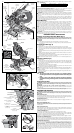
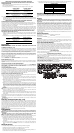
Cutting Picture Frames, Shadow Boxes And Other Four-
Sided Projects (Fig. 13, 14)
To best understand how to make the items listed here, we suggest that you try a few simple
projects using scrap wood until you develop a “feel” for your saw.
Your saw is the perfect tool for mitering corners like the one shown in Figure 13. Sketch A in Figure
14 shows a joint made by using the bevel adjustment to bevel the edges of the two boards at 45º
each to produce a 90º corner. For this joint the miter arm was locked in the zero position and the
bevel adjustment was locked at 45º. The wood was positioned with the broad flat side against the
table and the narrow edge against the fence. The cut could also be made by mitering right and left
with the broad surface against the fence.
Cutting Trim Molding And Other Frames (Fig. 14)
Sketch B in Figure 14 shows a joint made by setting the miter arm at 45º to miter the two boards
to form a 90º corner. To make this type of joint, set the bevel adjustment to zero and the miter arm
to 45º. Once again, position the wood with the broad flat side on the table and the narrow edge
against the fence.
The two sketches in Figure 14 are for four-sided objects only.
As the number of sides changes, so do the miter and bevel angles. The chart below gives the
proper angles for a variety of shapes.
– EXAMPLES –
NUMBER OF SIDES MITER OR BEVEL ANGLE
4 45°
5 36°
6 30°
7 25.7°
8 22.5°
9 20°
10 18°
The chart assumes that all sides are of equal length. For a shape that is not shown in the chart,
use the following formula: 180º divided by the number of sides equals the miter (if the material is
cut vertically) or bevel angle (if the material is cut laying flat).
Cutting Compound Miters (Fig. 15)
A compound miter is a cut made using a miter angle and a bevel angle at the same time. This is
the type of cut used to make frames or boxes with slanting sides like the one shown in Figure 15.
NOTE: If the cutting angle varies from cut to cut, check that the bevel lock knob and the miter
lock handle are securely locked. These must be locked after making any changes in bevel or miter.
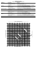
The chart at the end of this manual (Table 1) will assist you in selecting the proper bevel and miter
settings for common compound miter cuts. To use the chart, select the desired angle A (Fig. 15)
of your project and locate that angle on the appropriate arc in the chart. From that point follow
the chart straight down to find the correct bevel angle and straight across to find the correct miter
angle.
Set your saw to the prescribed angles and make a few trial cuts. Practice fitting the cut pieces
together until you develop a feel for this procedure and feel comfortable with it.
Example: To make a 4-sided box with 26º exterior angles (Angle A, Fig. 15), use the upper right
arc. Find 26° on the arc scale. Follow the horizontal intersecting line to either side to get miter
angle setting on saw (42°). Likewise, follow the vertical intersecting line to the top or bottom to
get the bevel angle setting on the saw (18°). Always try cuts on a few scrap pieces of wood to
verify the settings on the saw.
Cutting Base Molding (Fig. 16)
ALWAYS MAKE A DRY RUN WITHOUT POWER BEFORE MAKING ANY CUTS.
Straight 90º cuts:
Position the wood against the fence and hold it in place as shown in Figure 16. Turn on the
saw, allow the blade to reach full speed and lower the arm smoothly through the cut.
CUTTING BASE MOLDING FROM 3" UP TO 6.75" (76 mm to 171 mm) HIGH
VERTICALLY AGAINST THE FENCE
NOTE: Use the slide lock lever, shown in Figure 7, when cutting base molding measuring from 3"
to 6.75" (76 mm to 171 mm) high vertically against the fence.
Position material as shown in Figure 16.
All cuts should be made with the back of the molding against the fence and with the bottom of the
molding against the table.
INSIDE CORNER OUTSIDE CORNER
Left side
Miter left 45°
Save left side of cut
Miter right 45°
Save left side of cut
Right side
Miter right 45°
Save right side of cut
Miter left 45°
Save right side of cut
Material up to 6.75" (171 mm) can be cut as described above.
Cutting Crown Molding
Your miter saw is well suited to the task of cutting crown molding. In order to fit properly, crown
molding must be compound mitered with extreme accuracy.
The two flat surfaces on a given piece of crown molding are at angles that, when added together,
equal exactly 90º. Most, but not all, crown molding has a top rear angle (the section that fits flat
against the ceiling) of 52º and a bottom rear angle (the part that fits flat against the wall) of 38º.
Your miter saw has special pre-set miter latch points at 31.62º left and right for cutting crown
molding at the proper angle and bevel stop pawls at 33.86º left and right. There is also a mark on
the bevel scale at 33.9º.
The chart below gives the proper settings for cutting crown molding. (The numbers for the miter
and bevel settings are very precise and are not easy to accurately set on your saw.) Since most
rooms do not have angles of precisely 90º, you will have to fine tune your settings anyway.
FIG. 23
SCREWS
(two each side)
FIG. 24
SET
SCREW
SCREWS
FIG. 26
FIG. 25
BASE FENCE


Find Your Products By Category
Please Login
