
0
Owner's of the DeWalt Saw Double Bevel Sliding Compound Miter Saw gave it a score of 0 out of 5. Here's how the scores stacked up:
NOTE: Your saw is capable of cutting the following once a special setup procedure is followed.
Refer to Special Cuts.
0° miter Height 1.5" (38 mm) Width 16.1" (409mm)
45º miter Height 1.5" (38 mm) Width 11.7" (297mm)
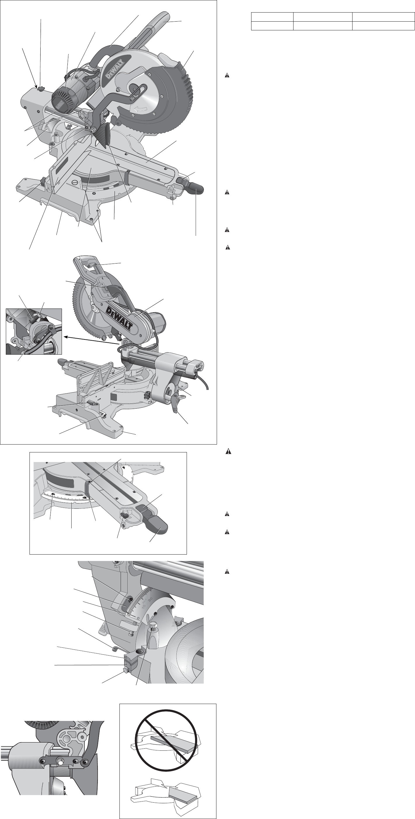
Familiarization
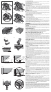
Your miter saw is fully assembled in the car ton. Open the box and lift the saw out by the
con venient lifting handle, as shown in Figure 2.
Place the saw on a smooth, flat surface such as a workbench or strong table.
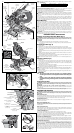
Examine Figure 4 to become familiar with the saw and its various parts. The section on adjus tments
will refer to these terms and you must know what and where the parts are.
CAUTION: Pinch hazard. To reduce the risk of injury, keep thumb underneath the operating
handle when pulling the handle down. The lower guard will move up as the operating handle is
pulled down, which could cause pinching. The operating handle is placed close to the guard for
special cuts.
Press down lightly on the operating handle and pull out the lock down pin. Gently release the
downward pressure and hold the operating handle, allowing it to rise to its full height. Use the lock
down pin when carrying the saw from one place to another. Always use the lifting handle to transport
the saw, or use the hand indentations shown in Figure 4.
Bench Mounting
Holes are provided in all 4 feet to facilitate bench mounting, as shown in Figure 4. (Two different-
sized holes are provided to accommodate different sizes of screws. Use either hole, it is not
necessary to use both.) Always mount your saw firmly to a stable surface to prevent movement. To
enhance the tool’s portability, it can be mounted to a piece of 1/2" (12.7 mm) or thicker plywood
which can then be clamped to your work support or moved to other job sites and reclamped.
NOTE: If you elect to mount your saw to a piece of plywood, make sure that the mounting
screws don’t protrude from the bottom of the wood. The plywood must sit flush on the work
support. When clamping the saw to any work surface, clamp only on the clamping bosses where
the mounting screw holes are located. Clamping at any other point will interfere with the proper
operation of the saw.
CAUTION: To prevent binding and inaccuracy, be sure the mounting surface is not warped or
otherwise uneven. If the saw rocks on the surface, place a thin piece of material under one saw
foot until the saw sits firmly on the mounting surface.
IMPORTANT SAFETY INSTRUCTIONS
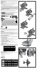
Changing or Installing a New Saw Blade (Fig. 3)
WARNING: To reduce the risk of serious personal injury, turn off the tool and disconnect
it from the power source before attempting to move it, change accessories or make any
adjustments.
CAUTION:
• Never depress the spindle lock button while the blade is under power or coasting.
• Do not cut ferrous metal (containing iron or steel) or masonry or fiber cement product with
this miter saw.
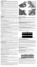
Removing the Blade (Fig. 3)
1. Unplug the saw.
2. Raise the arm to the upper position and raise the lower guard (A) as far as possible.
3. Loosen, but do not remove guard bracket screw (B) until the bracket can be raised far enough
to access the blade screw (E). Lower guard will remain raised due to the position of the guard
bracket screw.
4. Depress the spindle lock button (C) while carefully rotating the saw blade by hand until the lock
engages.
5. Keeping the button depressed, use the other hand and the wrench provided (D) to loosen the
blade screw. (Turn clockwise, left-hand threads.)
6. Remove the blade screw (E), outer clamp washer (F), blade (G) and blade adapter (H), if used.
The inner clamp washer (I) may be left on the spindle.
NOTE: For blades with a blade hole of 5/8" (15.88 mm), the 1" (25.4 mm) blade adapter(H) is not
used.
Installing a Blade (Fig. 3)
1. Unplug the saw.
2. With the arm raised, the lower guard held open and the guard bracket raised, place the blade
on the spindle, onto the blade adapter (if using a blade with a 1" [25.4 mm] diameter blade
hole) and against the inner blade clamp with the teeth at the bottom of the blade pointing
toward the back of the saw.
3. Assemble the outer clamp washer onto the spindle.
4. Install the blade screw and, engaging the spindle lock, tighten the screw firmly with wrench
provided (turn counterclockwise, left-hand threads).
NOTE: When using blades with a 5/8" (15.88 mm) diameter blade hole, the blade adapter will not
be used and should be stored in a safe place for future use. The separate blade adapter is not
available on all models.
5. Return the guard bracket to its original position and firmly tighten the guard bracket screw to
hold bracket in place.
WARNING:
• The guard bracket must be returned to its original position
and the guard bracket screw tightened before activating the
saw.
• Failure to do so may allow the guard to contact the spinning
saw blade resulting in damage to the saw and severe personal
injury.
Transporting the Saw
WARNING: To reduce the risk of serious personal injury, turn off the tool and disconnect
it from the power source before attempting to move it, change accessories or make any
adjustments.
WARNING: To reduce the risk of serious personal injury, ALWAYS lock the rail lock
knob, miter lock handle, bevel lock handle, lock down pin and fence adjustment knobs before
transporting saw.
In order to conveniently carry the miter saw from place to place, a lifting handle has been included
on the top of the saw arm and hand indentations in the base, as shown in Figure 4.
FEATURES AND CONTROLS
WARNING: To reduce the risk of serious personal injury, turn off the tool and disconnect
it from the power source before attempting to move it, change accessories or make any
adjustments.
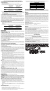
MITER CONTROL (FIG. 5)
The miter lock handle and miter latch button allow you to miter your saw to 60° right and 50° left. To
miter the saw, lift the miter lock handle, push the miter latch button and set the miter angle desired
on the miter scale. Push down on the miter lock handle to lock the miter angle.
TRIGGER SWITCH (FIG. 4)
The trigger switch turns your saw on and off. A hole is provided in the trigger for insertion of a
padlock to secure the saw.
MITER LATCH OVERRIDE (FIG. 5)
The miter latch override allows your saw to override the common stop angles. To override the
common stop angles, push the miter latch button and flip the miter latch override lever to the
vertical position.
BEVEL LOCK KNOB (FIG. 4)
The bevel lock allows you to bevel the saw 49° left or right. To adjust the bevel setting, turn the knob
counterclockwise. The saw head bevels easily to the left or to the right once the 0° bevel override
knob is pulled. To tighten, turn the bevel lock knob clockwise.
0° BEVEL OVERRIDE (FIG. 4)
The bevel stop override allows you to bevel the saw to the right past the 0° mark.
When engaged, the saw will automatically stop at 0° when brought up from the left. To temporarily
move past 0° to the right, pull the bevel lock knob. Once the knob is released, the override will be
reengaged. The bevel lock knob can be locked out by twisting the knob 180°.
When at 0°, the override locks in place. To operate the override, bevel the saw slightly to the left.
45° BEVEL STOP OVERRIDE (FIG. 6)
There are two bevel stop override levers, one on each side of the saw. To bevel the saw, left or right,
past 45°, push the 45° bevel override lever rearward. When in the rearward position, the saw can
bevel past these stops. When the 45° stops are needed, pull the 45° bevel override lever forward.
CROWN BEVEL PAWLS (FIG. 6)
When cutting crown molding laying flat, your saw is equipped to accurately and rapidly set a crown
stop, left or right (refer to Instructions for Cutting Crown Molding Laying Flat and Using the
Compound Features). The crown bevel pawl can be rotated to contact the crown adjustment
screw. The saw is factory set to be used for typical crown in North America (52/38), but can be
reversed to cut non-typical (45/45) crown. To reverse the crown bevel pawl, remove the retaining
screw, the 22.5° bevel pawl and the 33.86° crown bevel pawl. Flip the crown bevel pawl so the
30° text is facing up. Reattach the screw to secure the 22.5° bevel pawl and the crown bevel pawl.
The accuracy setting will not be affected.
FIG. 4
FIG. 6
22.5º BEVEL PAWL
(one each side)
BEVEL POINTER
(one each side)
0° BEVEL ADJUSTMENT
SCREW
BEVEL POINTER SCREW
(one each side)
BEVEL SCALE
CROWN ADJUSTMENT SCREW
(one each side)
45° BEVEL OVERRIDE LEVER
(one each side)
CROWN BEVEL
PAWL
(one each side)
45° BEVEL
ADJUSTMENT SCREW
(one each side)
KERF
PLATE
MOTOR
HOUSING
RAIL SET
SCREW
ADJUSTMENT
RAIL LOCK
KNOB
MOTOR
ENDCAP
BEVEL SCALE
LOCK DOWN
PIN
MITER
LATCH
BUTTON
TABLE
MITER LATCH
OVERRIDE
MITER
SCALE
MITER LOCK
HANDLE
FENCE
ADJUSTMENT
KNOB
(one each side)
BENCH MOUNTING HOLES
LIFTING
HANDLE
DUST DUCT
INLET
FENCE
HAND
INDENTATION
RAILS
OPERATING
HANDLE
LOWER
GUARD
BELT COVER
BEVEL LOCK
KNOB
TRIGGER
SWITCH
0° BEVEL
STOP
WING NUT
DEPTH
ADJUSTMENT
SCREW
DEPTH STOP
FENCE
ADJUSTMENT
KNOB
(one each side)
BLADE WRENCH
XPS
TM
ON/OFF
SWITCH
BASE
FIG. 5
MITER
POINTER
MITER
SCALE
SCREW
(4 places)
MITER POINTER SCREW
MITER
LATCH
BUTTON
MITER LOCK
HANDLE
MITER LATCH
OVERRIDE
FIG. 8
FIG. 7


Find Your Products By Category
Please Login
