
0
Owner's of the 3Com Gas Grill Extreme Series gave it a score of 0 out of 5. Here's how the scores stacked up:
Wiring (continued)
5
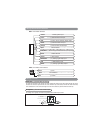
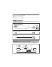
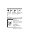
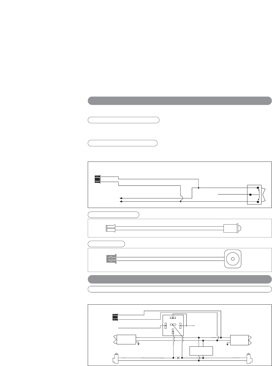
HC3: Black 3-Pin Door Lock Harness
Connect the Blue wire to the unlock wire from the door lock switch. If the door locking system is not a (-)
trigger system, additional relays will be required.
Blue Wire: (-) Door Unlock Control
Green Wire: (-) Door Lock Control
Connect the Green wire to the lock wire from the door lock switch. f the door locking system is not a (-) trigger
system, additional relays will be required.
3 Wire Ground Trigger Door Lock System
(
-
) Lock Out
Ground Input
(
-
) Unlock Out
To Door Lock
Control Relays
Lock Control
Switch
Blue Wire: Connect to Unlock
Green Wire: Connect to Lock
Black 3-Pin
Mini Connector
P2: Valet Switch
P1: LED Status Indicator
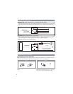
Optional Wiring Diagrams
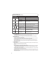
Red/White Wire: (When programmed for (-) 2nd Unlock Output)
When Programmed for this function, the Red/White wire provides a second (-) unlock output to unlock the
passenger’s doors. Use the “Blue Wire” on the Black 3 pin connector to unlock the drivers door.
Unlock Driver's Door First for 3-Wire Negative Door Lock Systems
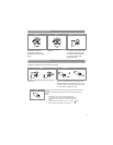
87
87A
85
86
30
Unlock Wire
Passenger's Door
Lock
Unlock
To +12V or Ground
To +12V or Ground
Driver's Door
Passenger's
Door Switch
Door Lock Relay
Control Module
Lock
Unlock
+12V
ALA984H
Relay
Driver's Door
Switch
Cut
Blue Wire
Green Wire
Red/White Wire


Find Your Products By Category
Please Login
