

0
Owner's of the 3Com Gas Grill Extreme Series gave it a score of 0 out of 5. Here's how the scores stacked up:

Parking
Lights
Only
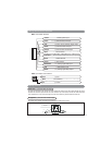
Piggyback
Connection
Headlight Switch
White Wire
4
Brown Wire: (-) Siren Output
Connect the brown wire to the Negative wire from an electronic siren (Siren Supplied). Connect t the remaining
wire from the siren to +12 volt. (Battery +)
The Brown wire can also be programmed for (-) horn honk output. (See Alarm Feature Programming to change
the setting)
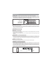
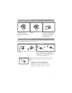
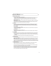
Red/White Wire: (-) 300mA Programmable Channel 3 Output (Default Trunk Release)
The Red/White wire is typically used to release the power trunk by remote. An additional relay is usually
required as shown in the diagram below. This wire can also be programmed for Domelight Supervision Control
or 2nd unlock function (See Alarm Feature Programming to change the setting)
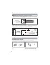
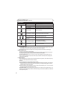
White Wire: (+/-) Parking Light Relay Output
Connect the white wire to the parking light wire coming from the headlight switch. Do not connect the white
wire to the dashboard lighting dimmer switch – Damage to the dimmer will result. Use a volt meter to test the
connection point before connecting the white wire. While checking, rotate the dimmer switch to make sure you
do not have the dimmer lead. The limitation of the white wire is 10 Amp max. Do not exceed this limit or
damage to the alarm and parking light relay will result.
The white/red wire is the input to the flashing parking light relay. The connection of the white/red wire will
determine the output polarity of the flashing parking light relay. Connect the white/red wire to (+) battery to have
(+) output from the relay or connect the white/red wire to chassis ground to have ground output from the relay.
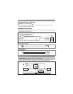
White/Red Wire: (+/-) Parking Light Relay Input
Vacant Socket: No Connection
Black Wire: Chassis Ground
This is main ground connection of the alarm module. Make this connection to a solid section of the vehicle
chassis. Do not connect this wire to any existing ground wires supplied by the factory wire loom, make the
connection to the vehicle’s chassis directly.
Red Wire: +12VDC Battery Input
Connect the Red wire directly to the (+) battery post for best operation of the alarm system.
87
86
85
30
Red/White Wire
(SPST ALA984H
Relay Not Supplied)
Output to Power Trunk Switch
To Constant +12 Volts
Input to Relay (+ or
-
)
Wiring (continued)


Find Your Products By Category
Please Login
