

0
Owner's of the 3Com Gas Grill Extreme Series gave it a score of 0 out of 5. Here's how the scores stacked up:

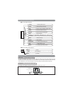
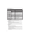

Component Installation . . . . . . . . . . . . . . . . . . . . . . . . . . . . . . . . . . . . . . . . . . . . . . . . . . . . . . . . . . . . . . . . 2
Wiring
White 12-Pin Main Harness. . . . . . . . . . . . . . . . . . . . . . . . . . . . . . . . . . . . . . . . . . . . . . . . . . . . . . . . . . . 2-5
Wiring Harness Quick Reference. . . . . . . . . . . . . . . . . . . . . . . . . . . . . . . . . . . . . . . . . . . . . . . . . . . . . . . 3
Black 3-Pin Door Lock Harness. . . . . . . . . . . . . . . . . . . . . . . . . . . . . . . . . . . . . . . . . . . . . . . . . . . . . . . . 6
Optional Wiring Suggestions . . . . . . . . . . . . . . . . . . . . . . . . . . . . . . . . . . . . . . . . . . . . . . . . . . . . . . . . . . . 5-6
Programming the Transmitter . . . . . . . . . . . . . . . . . . . . . . . . . . . . . . . . . . . . . . . . . . . . . . . . . . . . . . . . . . . 6-7
Alarm Feature Programming . . . . . . . . . . . . . . . . . . . . . . . . . . . . . . . . . . . . . . . . . . . . . . . . . . . . . . . . . . . . 7-8
Shock Sensor Testing and Adjustment . . . . . . . . . . . . . . . . . . . . . . . . . . . . . . . . . . . . . . . . . . . . . . . . . . . . 9
Owners Manual . . . . . . . . . . . . . . . . . . . . . . . . . . . . . . . . . . . . . . . . . . . . . . . . . . . . . . . . . . . . . . . . . . . . . . 9-12
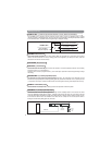
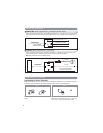
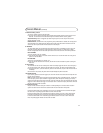
Mounting the Control Module:
Find a suitable location to secure the alarm control module within the passenger’s compartment of the vehicle.
Never mount the alarm control module in the engine compartment or in the trunk. In addition, never mount the
alarm control module in the direct path of the heater. Secure the alarm control module by using wire ties or drill
two 1/8" holes and secure the module to the frame of the vehicle with the screws provided.
Valet Switch
Select a mounting location for the switch that is easily accessible to the driver of the vehicle. The switch does
not have to be concealed. However, concealing the switch is always recommended, as this provides an even
higher level of security to the vehicle. Mount the valet switch in a hidden but accessible location. Route the valet
switch wires to the control module.
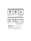
LED Status Indicator
The LED status indicator should be mounted in a highly visible area. Leave at least 6mm of space behind the
mounting location for LED housing. Once a suitable location is chosen, drill a 1/4" hole. Run the LED wires
through the hole then press the 2-pin LED housing into the place. Route the LED wires to the control module.
Antenna Wire
For maximum possible range, keep the antenna wire away from the alarm harnesses. Stretch out the antenna in
another direction and keep it as straight as possible. Do not connect the antenna wire to ground. Do not
lengthen or shorten the antenna wire. Do not coil or wind the antenna wire around another harness.
Table of Contents
Component Installation
2
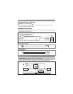
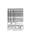
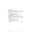
The main wire harness contains 11 wires which all have a specific purpose. Follow the wiring recommendations
enclosed for each wire. Wires not used should be released from the harness connector or taped off to prevent
accidental shorting.
HC4: White 12-Pin Main Harness
Wiring
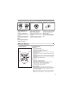
Yellow Wire: +12VDC Ignition Input
Connect the Yellow wire to a +12 volt wire that is switched on and off by the ignition key. The correct wire will
indicate +12 volts when the ignition key is in the on and start positions. Do not connect the yellow wire to the
“ACC” wire coming from the ignition switch.
Green Wire: (-) Common Door Pin Input
The green wire connects to the common wire of the vehicle that switches on the dome light. Normally this wire is
located at one of the door jamb switches. For some vehicles it may be necessary to connect the green wire directly
to the switched turn on wire at the dome light. The green wire connects to negative switched circuits only
.
Blue Wire: (-) Hood / Trunk / Auxiliary Trigger Input
The blue wire is an instant grounding trigger input for optional hood/trunk grounded pin switches or any
electronic sensor.


Find Your Products By Category
Please Login
