
0
Owner's of the Agilent Technologies Computer Hardware U2802A gave it a score of 0 out of 5. Here's how the scores stacked up:
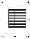
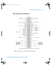
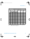


4 Product Specifications
50 Agilent U2802A 31-Channel Thermocouple Input User’s Guide
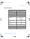
Overvoltage protection
i
TC Mode
ii
• Common mode: ±17 V (TC+ and TC– with
respect to GND)
• Differential mode: ±7 V (Differential voltage
between TC+ and TC–)
Bypass mode
• ±20 V (TC+ input with respect to GND)
Power Off Mode
• ±11 V (TC+, TC– input with respect to GND)
Input impedance > 1 G
Ω
Input bias current ±2.5 nA max
Input offset current ±1.5 nA max
Gain drift 60 ppm / °C max
Offset drift 1 µV / °C max
Filter cutoff frequency (–3 dB) (thermocouple
mode)
4.0 Hz
Filter type (thermocouple mode) Low Pass RC Filter
OTHER FEATURES
Recommended warm up time 30 minutes
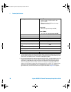
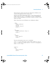
i The overvoltage protection levels specified above indicate the maximum voltage each input pin can
tolerate without resulting in any damages. However, prolonged exposure to these levels may affect
device safety and reliability. Hence, it should be avoided where possible.
ii On the channels configured for thermocouple mode, the TC+ and TC– pins can tolerate up to ±17 V
of differential voltage for a few minutes. However, exceeding ±100 mV voltage range on these
channels can cause additional current to be drawn from the device’s power supply regulators,
which may damage the device if multiple channels are overdriven for prolonged periods. This
applies to the case where a voltage source is tied across the TC
n
+ and TC
n
– pin. Voltage sources
greater than ±100 mV should be tied to TC
n
+ and GND (floating source), or TC
n
+ and TC
n+1
+
(grounded source), and have the channels set for bypass mode. Refer to Figure 2-5 on page 32.
U2802A_UG.book Page 50 Tuesday, January 8, 2008 10:24 AM


Find Your Products By Category
Please Login
