
0
Owner's of the Agilent Technologies Computer Hardware U2802A gave it a score of 0 out of 5. Here's how the scores stacked up:
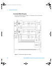
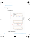
Features and Functions 2
Agilent U2802A 31-Channel Thermocouple Input User’s Guide 35
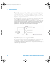
Open Thermocouple Detection
The U2802A provides a built- in 10 MΩ resistor on each TC+ terminal,
which is pulled up to the internal +15 V power supply rail. This resistor
can be enabled or disabled via the digital I/O pins on Rear Connector 2.
When enabled, this 10 MΩ pull-up resistor and the 10 MΩ pull- down
biasing resistor will cause the output from any unconnected thermocouple
input channels to saturate to the maximum output voltage. The U2355A
and U2356A devices can read this saturated channel and detect that a
particular channel has an open thermocouple input.
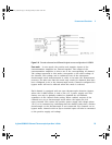
Trigger, Counter, External Timebase, and Analog Output
The U2802A provides a direct access to the analog and digital trigger
lines, counter channels, external timebase input, and analog output
channels from the U2355A and U2356A devices. These lines are routed
directly from the Rear Connector 1 and 2 to the J60 screw terminal
connector. Please refer to pin description for Connector J60 on page 43.
Precautions should be taken when driving high slew rate and frequency
clocks into the Counter and External Timebase lines to avoid excessive
noise coupling into other analog and digital lines. If excessive coupling or
crosstalk is observed, clock output drive strengths and slew rates should
be lowered to reduce coupling while still maintaining proper digital
function.
U2802A_UG.book Page 35 Tuesday, January 8, 2008 10:24 AM


Find Your Products By Category
Please Login
