
0
Owner's of the 2nd Ave. Coffeemaker DVPDNET-SL DeviceNet Network Scanner gave it a score of 0 out of 5. Here's how the scores stacked up:


DeviceNet Network Scanner DVPDNET-SL
DVP-PLC Operation Manual
7
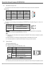
DVPDNET-SL.
z When DVPDNET-SL is operating, changing the setting of the function switch will be invalid.
z Use slotted screwdriver to adjust the DIP switch carefully in case you scratch the switch.
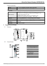
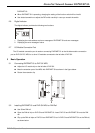
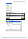
2.6 Digital Indicator
The digital indicator provides the following two functions:
DVPDNET
POWER
MS
NS
1. Displaying the node address and error messages of DVPDNET-SL and error messages.
2. Displaying the error message of slave.
2.7 I/O Module Connection Port
The I/O module connection port is used on connecting DVPDNET-SL to the left-side module conncection
port on DVP-SV PLC MPU or to other I/O modules connected to the left side of DVP-SV.
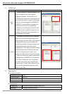
3 Basic Operation
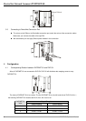
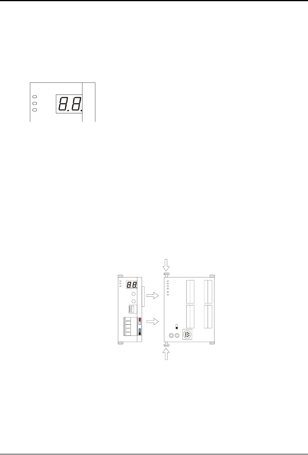
3.1 Connecting DVPDNET-SL to DVP-SV MPU
Adjust the I/O module clip on the left side of DVP-SV.
Meet the extension port of the MPU with DVPDNET-SL as shown in the figure below.
Fasten the extension clip.
DVPDNET DVP28SV
RUN
STOP
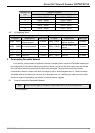
3.2 Installing DVPDNET-SL and DVP-SV MPU on DIN Rail
Use 35mm DIN rail.
Open the DIN rail clip on DVP-SV and DVPDNET-SL. Insert DVP-SV and DVPDNET-SL onto the DIN
rail.
Clip up the DIN rail clips on DVP-SV and DVPDNET-SL to fix DVP-SV and DVPDNET-SL on the DIN rail,
as shown below.


Find Your Products By Category
Please Login
