
0
Owner's of the 2nd Ave. Coffeemaker DVPDNET-SL DeviceNet Network Scanner gave it a score of 0 out of 5. Here's how the scores stacked up:

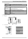

DeviceNet Network Scanner DVPDNET-SL
DVP-PLC Operation Manual
6
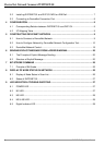
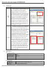
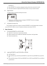
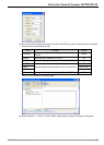
2.3 DeviceNet Connection Port
The connector is used on the connection to DeviceNet. Wire by using the connector enclosed with
DVPDNET-SL.
PIN Signal Color Content
1 V- Black 0 VDC
2 CAN_L Blue Signal-
3 SHIELD - Shielded
4 CAN_H White Signal+
5 V+ Red 24 VDC
1
2
3
4
5
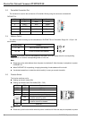
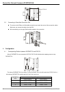
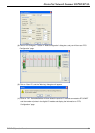
2.4 Address Switch
The switch is used on setting up the node address of DVPDNET-SL on DeviceNet. Range: 00 ~ 63 (64 ~ 99
are forbidden).
Switch setting Content
0 … 63 Valid DeviceNet node address
64…99 Invalid DeviceNet node address
9
1
6
4
5
0
0
9
1
3
2
7
8
2
5
6
4
3
7
8
Example: If you need to set the node address of DVPDNET-SL to 26, simply switch the corresponding
switch of x10
1
to 2 and the corresponding switch of x10
0
to 6.
Note:
z Please set up the node address when the power is switched off. After the setup is completed, re-power
DVPDNET-SL.
z When DVPDNET-SL is operating, changing the setting of node address will be invalid.
z Use slotted screwdriver to rotate the switch carefully in case you scratch the switch.
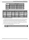
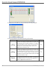
2.5 Function Switch
The function switches are for:
Setting up the work mode (IN0)
Setting up the baud rate of DeviceNet (DR0 ~ DR1)
DR1 DR0 Baud rate
OFF OFF 125 kbps
OFF ON 250 kbps
ON OFF 500 kbps
ON ON Incorrect setting
ON
When the slave is off-line, the I/O data in
the buffer area will be held.
IN0
OFF
When the slave is off-line, the I/O data in
the buffer area will be cleared.
IN1 Reserved
Note:
z Please set up the function switch when the power is switched off. After the setup is completed, re-power


Find Your Products By Category
Please Login
