
5.0
Owner's of the A.O. Smith Boiler VB/VW- 1000 gave it a score of 5.0 out of 5. Here's how the scores stacked up:
16
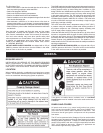
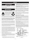
VENTING
VENT SIZING, INSTALLATION AND TERMINATION SHALL
BE IN ACCORDANCE WITH THIS INSTALLATION MANUAL.
ALL ELECTRICAL POWER AND GAS MUST BE TURNED OFF
PRIOR TO ANY INSTALLATION OF THE VENTING SYSTEM.
SPECIAL INSTALLATION CONSIDERATIONS
This boiler is a category IV appliance that can be vented using room
air for intake combustion air, or direct vented so that all intake air for
combustion comes from the outside through a sealed pipe. When
installing this boiler as direct vent, special vent kits are required.
Incoldclimatesanywatervaporremainingintheuegaseswillcondense
into a cloud of vapor at the point where the vent system exits the building.
Special consideration is recommended, before locating the vent termination
near walkways, windows and building entrances.
Direct venting into dead spaces such as alleys, atriums, and inside
cornerscancauserecirculationofuegases.Recirculationofue
gases will cause sooting, premature failure of the heat exchanger,
and icing of the combustion air intake during severe cold weather.
Topreventtherecirculationofuegases,maintainasmuch
distance as possible between the combustion air intake and the
exhaustventterminal.Duetolargevolumesofuegases,multiple
boiler applications also require additional distance between the
intake and exhaust terminals.
VENTING SYSTEM USING AL 29-4C
®
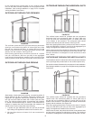
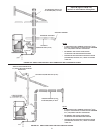
This boiler may be installed in four separate orientations depending
on the require ments of the building and the appliance. The installer
must decide which method is most appro priate for each installation.
These orientations are:
1. Vertical Termination - vertical vent termi na tion through un-
enclosed or en closed areas with roof penetration, see Figure 11.
2. Through-the-Wall Termination (TWT) - hori zontal vent
termination directly through an outside wall, see Figure 11A.
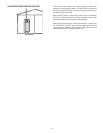
3. Horizontal Direct Vent-usingTWTtoexhaustueproducts
and PVC piping to bring combus tion air to the boiler from the
outside, see Figures 12 and 12C.
4. Vertical Direct Vent - using a vertical vent termination to exhaust
ueproductsandPVCpipingtobringcombustionairtothe
boiler from outside, see Figures 12A and 12B.
GENERAL EXHAUST VENT INSTALLATION PROCEDURE
Prior to beginning the installation of the vent system, deter mine and
obtain all parts re quired for the installa tion. IF THIS INSTALLATION IS
A DIRECT VENT INSTALLATION A DIRECT VENT KIT IS REQUIRED.
REFER TO THE PARTS LIST FOR KIT NUMBER.
Proper operation of the boiler and vent ing system is dependent
uponuseofallspeciedpartsandinstallationtechniques;both
safety and proper perfor mance of the system may suffer if
instructions are not followed.
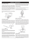
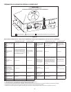
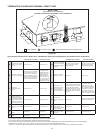
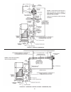
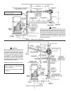
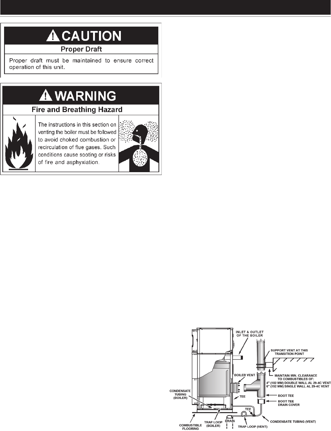
CONNECTING VENT TO BOILER
Referring to Figure 10., combustion gases are vented using AL29-
4C material. Transition from the horizontal outlet to a vertical vent
is achieved through the use of a boot-tee and drain cover or other
engineering approved arrangement. A support bracket should be
located at the transition point.
The drain connection is necessary for the removal of condensate
whichmayforminthestack.Arubberhose3/8”IDand10feet
long is provided for directing the condensate to a suitable drain.
1. Attach the Boot Tee Drain Cover to the appropriate leg of the
Boot-Tee, see Figure 10.
2. A trap loop must be formed into the drain tube simply by looping
thetubetoaminimum3inch(76mm)diameterandsecurethe
loop with a cable tie, see Figure 10.
3. Priortonalassemblythetraploopmustbe“primed”bypouring
a small quan tity of water into the drain hose.
4. ConnecttheBoot-TeeandDrainTeeassembly(orengineering
approvedequivalent)totheboilerventconnector,seeFigure10.
5. Attachthehosetothedrainttingandrunthehosetoasanitary
sewer drain maintaining the proper trap loop and following all
local, state and federal codes and regulations for draining of
acidicefuent(condensate).
Figure 10.


Find Your Products By Category
Please Login
