
0
Owner's of the A.O. Smith Boiler NW 37-670 gave it a score of 0 out of 5. Here's how the scores stacked up:
9
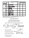
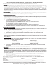
WIRING DIAGRAM 480V THREE-PHASE (WYE)
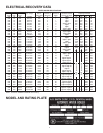
SYSTEM CLEANING
The hot water system should be internally cleaned and flushed to
remove contaminants which may have accumulated during installation.
System cleaning provides chemical stability necessary for component
life and system performance.
Failure to clean the system may cause:
1. Poor heating due to formation of gas.
• Residual pipe dope, thread cutting oil, solder flux, dirt and
other foreign materials breakdown to form gas. This is
indicated by a continuing need for purging even through
the system is “closed”.
2. Pump seal leakage.
• Acidic water (low pH) and contamination such as soil and
sand result in premature or recurring pump seal failures.
3. Automatic air valve leakage.
• Contaminants cause sticky sealing surfaces and result in
leakage.
4. Relief valve operation.
• Gas formation increases system pressure and relief valve
spillage.
5. Water leaks at joints and fittings.
• Corrosion and eventual failure of connections occur when
system pH is low.
6. Noisy operation.
• Heat transfer surfaces can be fouled with dirty, oily water.
This plus gas lead to noisy water circulation.
WARNING
Be sure to turn off power when working on or near the electrical system
of the boiler. Never touch electrical components with wet hands or
when standing in water. When replacing fuses always use the correct
size for the circuit.
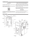
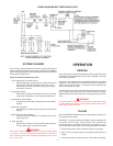
OPERATION
GENERAL
Never operate the heating elements without being certain the boiler
is filled with water and a pressure relief valve is installed in the relief
valve opening provided.
An electronic type low water cutoff is provided on all boilers as standard
equipment. The water probe is installed near the top of the tank to
monitor the presence of water. The control circuit is opened if the
water level is below this point.
The pilot switch on the cabinet front permits the boiler to be turned on
and off without having to operate the electrical disconnect switch.
Additional switches may be provided for manually operating contactor
coils.
WARNING
Full power is present whenever the cabinet door is opened even with
the pilot switch(es) turned off. Never operate the boiler with cabinet
doors open or panels removed.
FILLING
Refer to SYSTEM CLEANING section for preparing the system prior
to final filling and operation.
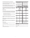
Hard Water: in areas which have hard water it may be desirable to fill
the system with soft water and/or provide water treatment as
recommended by a consultant familiar with local conditions. In this
way harmful water scale build-up on the heating elements is minimized.
1. Close the boiler drain valve and system valves as necessary.
2. Open a vent in the highest point of the system to allow the air to
escape.
3. Fully open the make-up water inlet valve. Fill the boiler and piping.


Find Your Products By Category
Please Login
