
0
Owner's of the Applied Energy Products Ventilation Hood XX100T gave it a score of 0 out of 5. Here's how the scores stacked up:

Xodus Toilet/Bathroom Fans XX100, XX100P & XX100T installation & operating
instructions. Please leave this leaflet with the fan for the benefit of the user.
Installing the fan
These appliances are intended for connection to fixed wiring. Check that the
electrical rating shown on each fan matches the mains supply.
THESE APPLIANCES ARE DOUBLE INSULATED AND DO NOT REQUIRE AN EARTH
CONNECTION.
All installations must be supervised by a qualified electrician. Installations and
wiring must conform to current IEE Regulations (UK), local or appropriate
regulations (other countries).
If you have any queries before installing these products or after they have been installed,
contact the Xpelair Technical Hotline (details overleaf), or outside the UK contact your
distributor.
Description
XX100 Range fans have the following features:
• Single speed operation.
XX100 • Operate the fan using an on/off switch (not supplied).
XX100P • Operate the fan using an integral pull cord.
XX100T • Built-in timer operates fan for a preset delay of 20 minutes.
What the installer will need
• A double pole isolating switch with a minimum contact gap of 3mm in each pole (wall or
ceiling mounted).
• If metal switch boxes are used, earthing regulations must be followed.
• Suitably rated 2-core cable - XX100 / XX100P.
• Suitably rated 3-core cable - XX100T.
• 3mm electricians screwdriver and No. 1 or No. 2 Pozidriv screwdrivers.
• 3 off No. 8 wall screws and plugs or appropriate fasteners.
• A wall or ceiling on/off switch - XX100T. It is recommended to use a switch with an
indicator light.
• To prevent a possible hazardous situation from water ingress, an appropriate
condensation trap (Xodus XCT100) must be fitted as close as possible to the fan
in all situations where any section of the ductwork is positioned higher than the
fan itself.
If wall mounting the fan you will also need
• XXWK4 Wall Kit including telescopic wall tube and back draught shutter.
• Alternatively, a CFWG100 Wall Grille and 100mm diameter ducting.
• Masonry drill, hammer and chisel (or core drill equipment if available).
• Mortar to make good the hole around the ducting.
If window/panel mounting the fan you will also need
• XXGK4 Glass Kit.
• You will need a window pane between 3mm and 6mm thick (preferably 4mm).
• Do not install in glass 3mm thick if the window pane area is more than 0.2 sq. m.
• If installing in sash windows you should mount the fan in the upper window. Secure the
upper sash in the closed position and fit stops just below the level of the fan, to prevent
damaging it when the sash is raised.
• If ceiling mounting the fan, an XXCK4 Ceiling Kit is required and appropriate ancillaries
for termination.
For example:
1. Termination ducting kit.
2. Soffit board termination grille.
3. 100mm diameter flexible ducting. If installing in a vent, an XXVK4 Vent Kit is required.
Where to locate the fan
• Locate it as high as possible.
• At least 110mm from the edges of the wall mounting surface to the centre of the hole.
• As far away as possible from and opposite to the main source of air replacement to
ensure airflow across the room (eg. opposite the internal doorway).
• Near the source of steam or odours.
• Not where ambient temperatures are likely to exceed 50
o
C.
• If installed in a kitchen fans must not be mounted immediately above cooker hob
or eye level grille.
• If installing in a room containing a fuel burning device which has a non-balanced
flue, it is the installer's responsibility to ensure that there is enough replacement
air to prevent fumes being drawn down the flue when the fan is operating up to
maximum extract. Refer to local Building Regulations for specific requirements.
• Exhaust air must not be discharged into a flue used for exhausting of fumes from
appliances supplied with energy other than electric. Requirements of all authorities
concerned must be observed for exhaust air discharge and intake flow rates.
• When intended for use in possible chemical corrosive atmospheres, consult our
Technical Department or your distributor.
• This electrical product is rated at "IPX5", and can be installed anywhere in a
shower room or bathroom.
Installing the isolating switch & cables
1. Check that the electrical rating shown inside the backplate matches your mains supply.
2. Check there are no buried pipes or cables e.g. electricity, gas, water behind the switch
location (in the wall or above the ceiling). If in doubt seek professional advise.
3. Isolate the mains supply.
4.
Lay in the cable from the isolating switch to the fan location via the on/off switch (if required).
5. Lay in the cable from the isolating switch to the point of connection to the mains supply.
Warning: Do not make any connections to the electrical supply at this stage.
6. Install the isolating switch and on/off switch (not supplied).
7. Make all connections within the isolating switch and the on/off switch (if required).
Note: on/off switch must be situated so that it cannot be touched by persons
making use of the bath or shower.
WARNING: DO NOT MAKE ANY CONNECTIONS TO THE ELECTRICAL SUPPLY AT
THIS STAGE.
If in doubt, seek professional advice.
Preparing the hole
If working above ground floor level, appropriate safety precautions must be
observed.
WARNING: EYE PROTECTION MUST BE WORN DURING ALL DRILLING AND
CHISELLING OPERATIONS.
If installing in a wall
1. Check there are no buried pipes or cables in the wall or obstructions on the
outside e.g. electricity, gas, water.
2. Mark on the wall the centre of the duct hole. The centre of the hole should be at least
110mm away from the edge of the mounting surface.
3. Use this centre to mark a circle to suit the wall duct (115mm diameter).
If core drill equipment is available:
4. Use as directed by core drill manufacturer.
If core drill equipment is not available:
4. Drill a centre hole right through the wall.
5. Cut the hole. Do not cut right through the wall. (The recommended method is to drill a
series of holes, close together, around the edge of the cutting line and remove the brick
between the holes with a chisel).
6. Go outside and cut a hole in the outer wall, repeating the process described above.
7. Cut ducting to the correct length if required.
8. Fit the ducting. Ensure that the duct slopes down away from the fan to allow drainage of
any incoming rain water to the outside.
9. Make good the hole around the ducting. Allow the mortar to set before continuing with
the fan installation.
If installing in a window or panel
1. Cut a hole, 125mm in diameter or if installing in a window, obtain a ready cut pane.
2. The centre of the hole should be at least 110mm away from the edge of the panel or
pane of glass.
If installing in a ventilation shaft
1. Check there are no buried pipes or cables in the ventilation shaft.
If in doubt seek professional advice.
2. Cut a hole 110mm in diameter, in the side of the shaft.
If installing in a ceiling
1. Check there are no buried pipes or cables in the ceiling above the fan location.
If in doubt seek professional advise
2. Cut a hole 115mm diameter.
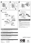
Preparing the fan for installation
Remove the front cover by pressing the release catches located on the sides of the unit
with a 3mm screwdriver, whilst pulling the front cover forward (fig E).
Mount the fan in the hole
If working above ground floor level, appropriate safety precautions must be
observed.
If installing in a wall, ceiling or vent
Mark the position of the back plate (fig A)
1. Hold the backplate so that the terminal block faces you in the top left hand corner and
the lip points towards the hole.
2. Carefully insert the lip into the wall duct/ceiling or vent shaft.
3. Adjust the position of the back plate until it is level.
4. Mark on the wall/ceiling or vent shaft the positions of the three fixing holes in the back
plate.
5. Remove the back plate from the ducting.
6. Drill screw holes in these positions if necessary, and fit wall plugs if necessary.
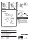
Mount the back plate (fig B)
1a.
If installing in a vent, an XXVK4 Vent Kit is required.
Follow instructions provided.
1b.
If installing in a ceiling, an XXCK4 Ceiling Kit and termination ancillaries are required.
Follow instructions provided.
2. If wiring the fan from behind, remove knockout. Feed the mains cable entry hole in the
backplate to the terminals (Fig C).
3. If wiring from above, leave the cable free to be fitted into labyrinth.
4. Insert the lip of the back plate into the wall duct/ceiling or vent shaft as before.
5. Fasten the back plate to the wall/ceiling or vent shaft using appropriate fasteners.
If using screws, do not overtighten.
6. If installing in a wall, a CFWG100 Wall Grille is required. Follow instructions provided.
If installing in a window or panel
1. If installing in a window or panel no more than 9mm thick, a XXGK4 Glass Kit is
required. Follow instructions supplied.
Wire the electrical connections
• Make sure the mains supply is isolated.
• All wiring and installation must be supervised by a qualified electrician.
1. Wire the fan as shown in fig D. Check fan model for correct diagram. Feed the cable
between the two raised pegs, if wiring from above, and through labyrinth to terminal
block.
2. Switch off the mains electrical supply and remove fuses.
3. Connect the cable from the isolating switch to the electrical supply wiring.
•
For fixed wiring circuits the protective fuse for the appliance must not exceed 5A.
All Fans
• If wiring from above, cut out the cable entry slot marked on top of the front cover.
• Fit the front cover by aligning it square to the duct and pushing it onto the backplate
until the release catches snap into the slots on the front cover.
• Refit the fuses and switch on the mains supply.
Operating the fan
XX100 only
• Operate the fan using the on/off switch. Repeat to turn off.
XX100P only
• Operate the fan by pulling and releasing the cord. Repeat to turn off.
XX100T only
•
Operate the fan using an on/off switch. When the switch is turned off, the fan continues
to operate for the set time delay.


Find Your Products By Category
Please Login
