
0.2
Owner's of the 3M Carbon Monoxide Alarm MACURCO gave it a score of 0.2 out of 5. Here's how the scores stacked up:
4. When using the GD-2A with normally closed initiating circuits, use the Com. and
N.C. alarm relay connections.
5. See wiring diagram and information below for connections of the GD-2A.
UL 2075 Requirements - 12.4.1 Power supply leads provided for field
connection shall not be less than 6 inches (152 mm) long, provided with
strain relief, and shall be no smaller than 18 AWG (0.82 mm
2
). The insulation,
when thermoplastic, shall not be less than 1/32 inch (0.8 mm) thick.
Exception No. 1: A lead is not prohibited from being less than 6 inches long
when it is evident that the use of a longer lead results in damage to the
insulation.
Exception No. 2: Solid copper leads as small as 26 AWG (0.13 mm
2
) are not
prohibited from use when:
A. The current does not exceed 1 ampere for lengths up to 2 feet
(61 cm) and the current does not exceed 0.4 ampere for lengths from
2 feet (61 cm) up to 10 feet (3.05 m);
B. There are two or more conductors and they are covered by a common
jacket, or the equivalent; and
C. The assembled conductors comply with the requirements of the Strain
Relief Tests, Section 18.
12.4.2 Leads provided for field connection to power limited signaling circuits,
such as those employed for connection to remote signaling devices, shall not
be smaller than 16 AWG (1.3 mm
2
), for a single conductor; 19 AWG
(0.65 mm
2
) for two or more conductors; and 26 AWG (0.13 mm
2
) for four or
more conductors of a multi-conductor cable. The conductor shall be solid,
bunch tinned stranded, or stranded copper. Stranded copper wire consisting
of not more than seven strands shall be employed only for 18 AWG
(0.82 mm
2
) and larger conductors.
6. The GD-2A uses a full wave bridge rectifier at its power input, so that it is
independent of the polarity of the input power. It can operate on DC or AC
voltages between 12 and 24 volts.
7. A switching regulator is used to efficiently match the wide input voltage range
to the fixed, internal power system. As a result the power consumption is fairly
constant at about 0.75 watts in normal operation, and 1.0 watt in alarm.
8. The alarm control panel zone inputs must be terminated with end of line
resistors (E.O.L.R.), which are provided with the panel. The GD-2A does not have
an internal audible sounder and must be connected to a UL Listed Fire Alarm/
Burglary Control Panel with a UL Listed audible device that provides at least 85
dB sound output.
POWER UP
When the unit is powered up it performs a self-test during which the green
LED light blinks for a period of one and one half to two minutes. Afterwards,
the green LED light will turn on continuously to indicate the unit is in normal
operation (ARMED). If the self-test fails or the green LED light does not turn
on continuously do not use. Failure to do so may adversely affect product
performance and result in sickness or death.
When power is first applied to the detector, it will go through a warm-up period of one
and one half to two minutes, during which alarms are inhibited. The green LED light
will turn on and off during the delay period. The green light will turn on continuously
(ARMED) afterwards to indicate the unit is in normal operation.
OPERATION
1. Once the GD-2A is operational (ARMED) the green light will be on continuously. If
gas is detected the red LED (ALARM) turns on and the SPDT alarm relay activates
to indicate the alarm condition.
2. In the configuration, as shipped from the factory, the GD-2A is self-restoring.
When the air clears of gas, the red light turns off and the relay switches to its
normal state. A jumper wire on the circuit board can be clipped to allow the unit
to latch in upon alarm. Once latched in, power will need to be interrupted to
un-latch the alarm condition.
• The GD-2A can be modified, either before or after installation, to have a
latching output. Pull off the cover and locate the jumper wire labeled “CLIP
FOR LATCH IN” on the printed circuit board in the upper right hand side. Clip
or cut this jumper wire and separate the wire ends. Now the unit will stay
in alarm (once gas has exceeded the pre-set threshold) until the power is
interrupted. When replacing the cover, make sure the lights line up with their
access holes.
3. The GD-2A has a supervisory circuit of critical functions. A trouble condition, due
to failure of a non-reliable component, results in both lights switching on and off
and the normally closed trouble relay opening. A power failure also causes the
trouble relay to open.
ALARMS
Immediately exit any environment if there is an alarm condition on the detector.
Failure to do so may result in sickness or death.
The final alarm is determined by the configuration of the control panel, with the
GD-2A only switching its relay to actuate the panel. Do not connect the GD-2A to Fire
Alarm Circuits, or Burglar Alarm or other signals. The illumination of the red (ALARM)
light on the GD-2A indicates the alarm condition. When an alarm occurs immediately
evacuate the premises and seek assistance.
In addition to the methane (natural gas) and propane (LP) gas that it is designed
to detect, the GD-2A can also be affected by a broad range of combustible gases.
Some of these that may cause an alarm are: alcohols, ammonia, cleaning solvents,
paint thinner, gasoline vapors, and aerosol propellants. Aerosol cans such as hair
spray usually contain a combustible gas. Always make sure that there is adequate
ventilation when you use these products. Proper location, not in kitchens or
bathrooms, will minimize alarms due to normal use of household products.
This detector will only indicate the presence of combustible gas at the sensor.
Combustible gas may be present in other areas. Accommodation spaces should
be well ventilated when household cleaning supplies or similar contaminants
are used.
TROUBLE INDICATOR
The trouble signal is determined mostly by the configuration of the alarm panel, with
the GD-2A trouble relay only providing an open circuit for actuation. A failure of the
gas-sensing element will result in both lights turning on and off and the trouble relay
opening. Failure of power supplies in the GD-2A or a lack of power to the detector will
result in the trouble relay opening. The most common expected trouble would be a
break in the wiring between the panel and the GD-2A. When a trouble signal occurs
call the alarm panel installer for assistance.
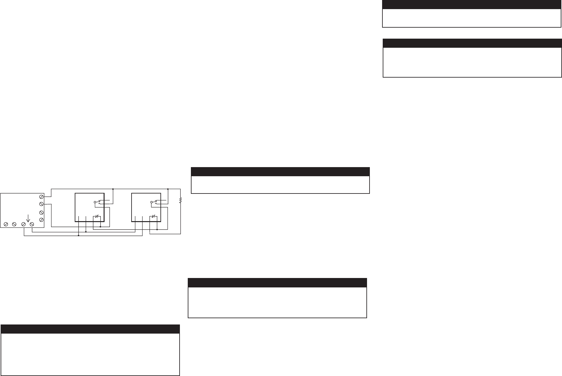
TYPICAL CONNECTION OF TWO GD-2A TO AN ALARM CONTROL PANEL
Alarm Control Panel
GD-2A
Battery back-up 12 or
24VDC Power supply.
Fuse or current limit at
1.0VA for each GD-2A
N.O. initiating
circuit
POWER
12/24V
SPDT
alarm
relay
Trouble
relay N.C.
GD-2A
POWER
12/24V
E.O.L.R.
SPDT
alarm
relay
Trouble
relay N.C.
W WARNING
W WARNING
W WARNING
W WARNING
W WARNING
Do not cover or obstruct visual alarm LED. Doing so may adversely affect
product performance and result in sickness or death.
MAINTENANCE
Do not disassemble unit or attempt to repair or modify any component of
this instrument. This instrument contains no user serviceable parts, and
substitution of components may impair intrinsic safety which may adversely
affect product performance and result in sickness or death.
The GD-2A does not require regular maintenance. The unit uses a self-purging
semi-conductor sensor that has a long life expectancy (7-10 year life). All service
and repair of the GD-2A are to be performed by 3M. 3M does not sanction any
third-party repair facilities.
TESTING
Once the unit is fully operational (the green light is on steady), test the unit by
directing gas from an unlighted butane cigarette lighter into the detector near the
left hand side through one of the vent holes. It will be necessary to hold the lighter
valve open for several seconds. The red light (ALARM) will turn on, the alarm relay
switches, and any devices connected should activate. The detector should be tested
regularly by using gas from an unlit cigarette lighter, as detailed above.
CLEANING
The GD-2A should be cleaned using the soft brush attachment of your vacuum
cleaner. The GD-2A should be tested after cleaning to ensure the unit is operating
normally.
SENSOR POISONS
The gas sensor tip in the detector is designed with extreme sensitivity to the
environment. As a result, the gas sensor may deteriorate if it is exposed to a direct
spray from aerosols such as paints, silicone vapors, etc., or to a high density of
corrosive gases (such as hydrogen sulfide, sulfur dioxide) for an extended period of
time.
3M FIXED GAS DETECTION PRODUCTS LIMITED WARRANTY
3M warrants the GD-2A gas detector will be free from defective materials and
workmanship for a period of two (2) years from date of manufacture (indicated on
the inside cover of the GD-2A), provided it is maintained and used in accordance
with 3M instructions and/or recommendations. If any component becomes defective
during the warranty period, it will be replaced or repaired free of charge, if the
unit is returned in accordance with the instructions below. This warranty does not
apply to units that have been altered or had repair attempted, or that have been
subjected to abuse, accidental or otherwise. The above warranty is in lieu of all
other express warranties, obligations or liabilities. THE IMPLIED WARRANTIES OF
MERCHANTABILITY AND FITNESS FOR PARTICULAR PURPOSE ARE LIMITED TO A
PERIOD OF TWO (2) YEARS FROM THE PURCHASE DATE. 3M shall not be liable for
any incidental or consequential damages for breach of this or any other warranty,
express or implied, arising out of or related to the use of said gas detector.
Manufacturer or its agent’s liability shall be limited to replacement or repair as
set forth above. Buyer’s sole and exclusive remedies are return of the goods and
repayment of the price, or repair and replacement of non-conforming goods or parts.
FOR MORE INFORMATION
In United States, contact:
Website: www.3M.com/OccSafety
Technical Assistance: 1-800-243-4630
For other 3M products:
1-800-3M-HELPS or 1-651-737-6501


Find Your Products By Category
Please Login
